- 8777701917
- info@saikatinfotech.com
- Basirhat W.B

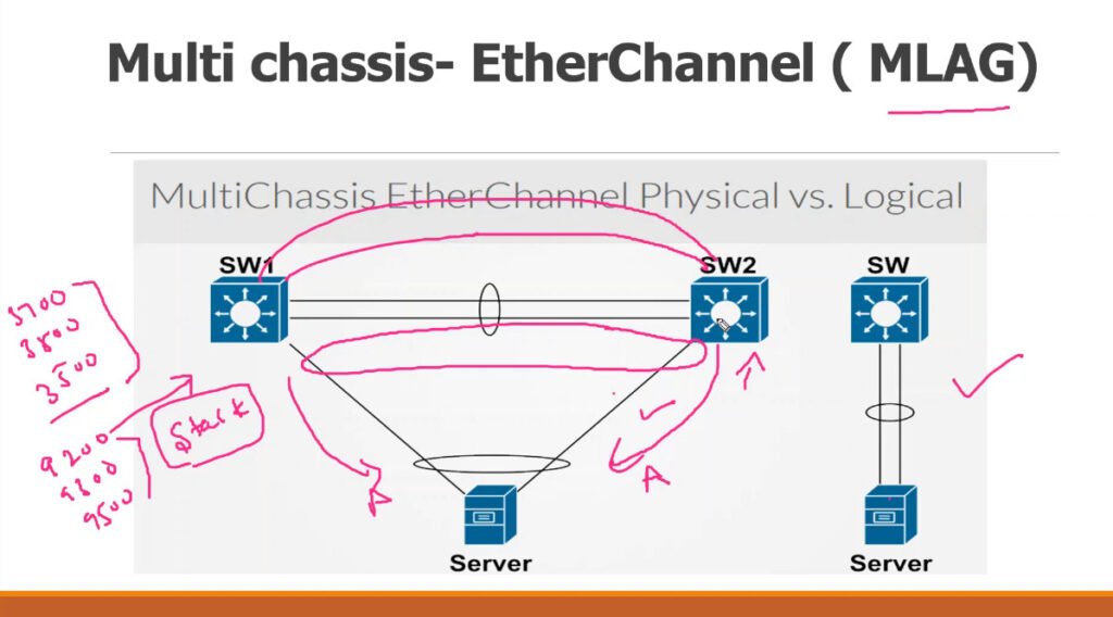
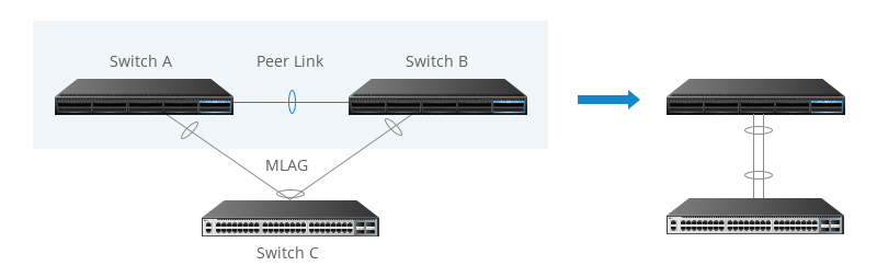
Multi-Chassis EtherChannel (MLAG) is a network design concept where two (or more) physical network devices (usually switches) act as a single logical entity for the purpose of creating a high-availability and load-balanced network link. This method is commonly used in data centers and large enterprise networks to provide redundancy and increase bandwidth.
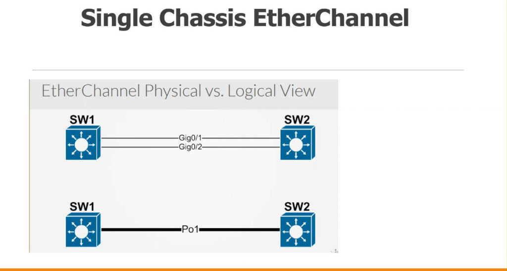
In an EtherChannel, multiple physical links between switches or between a switch and a server are bundled together to form a single logical connection. The goal of MLAG is to allow these aggregated links to appear as a single logical link to the connected devices while still maintaining the advantages of redundancy, fault tolerance, and increased throughput.
In a data center, MLAG could be used to connect two aggregation switches to multiple server racks. The servers would each connect to both aggregation switches through two separate physical links (configured as part of an EtherChannel). If one of the aggregation switches fails, the traffic can continue to flow through the other switch, ensuring network reliability.
Would you like more details on how MLAG works in practice with a specific vendor’s equipment?
In the era of digital transformation, data centers have become the cornerstone of enterprise operations, enabling everything from cloud computing to big data analytics. As businesses expand and their network traffic grows exponentially, ensuring high availability, scalability, and operational efficiency within data centers is more critical than ever. Multi-Chassis Link Aggregation Group (MLAG) has emerged as a pivotal technology to address these needs, providing robust solutions for network redundancy, load balancing, and simplified management. This article will delve into the fundamental concepts of MLAG, explore its diverse applications, and discuss its crucial role in modern data center network design.
MLAG Overview
Multi-Chassis Link Aggregation Group (MLAG) is a sophisticated networking technology that enhances traditional Link Aggregation Group (LAG) by allowing link aggregation across multiple switches. This architecture significantly improves network performance and reliability by providing enhanced redundancy and load balancing.
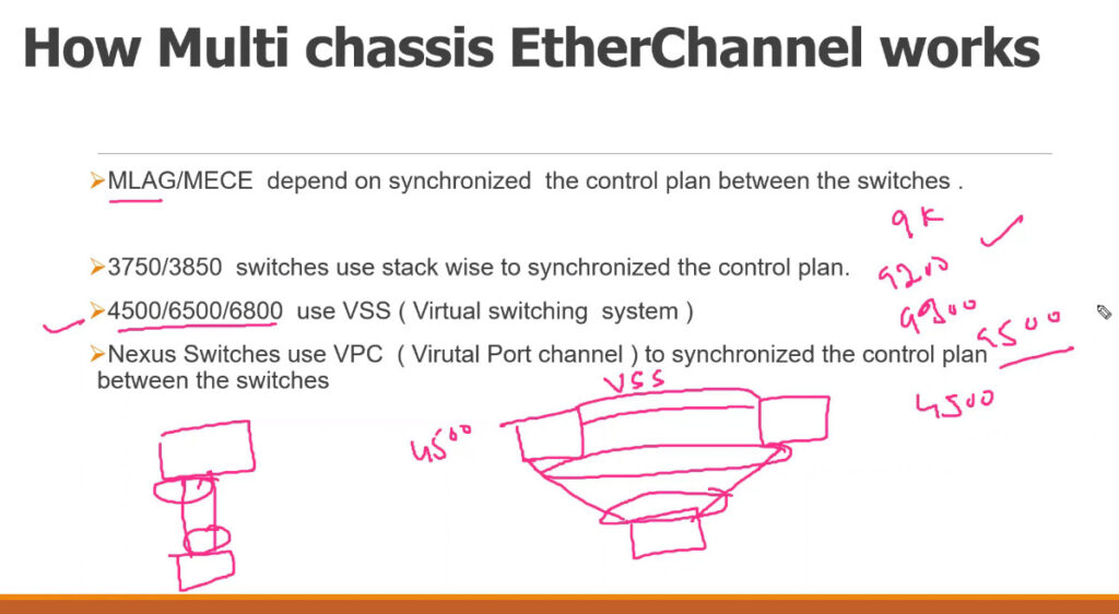
MLAG functions by presenting two or more physical switches as a single logical switch to connected devices. This is made possible through synchronization protocols and control mechanisms that ensure coordinated operation of the switches. Key components of MLAG include:
Control Plane Synchronization: Ensures that MLAG peers maintain consistent forwarding states and configurations.
Data Plane Operations: Facilitates efficient data transfer across aggregated links, balancing the load and ensuring seamless failover capabilities.
Keep Alive Mechanisms: Monitors the health of MLAG peers, detecting failures and triggering appropriate responses to maintain network stability.
Is MLAG the Same as LACP?
While MLAG (Multi-Chassis Link Aggregation Group) and LACP (Link Aggregation Control Protocol) both aim to enhance network performance and reliability through link aggregation, they are not the same. They differ in their scope, operation, and use cases. Here’s a comparison to highlight their distinctions:
Scope and Operation
MLAG:
Scope: Operates across multiple switches, treating them as a single logical switch to connected devices.
Redundancy: Provides high redundancy by allowing failover between switches.
Load Balancing: Distributes traffic across multiple switches.
Management Complexity: Requires more complex configuration and synchronization between multiple switches.
Scalability: More scalable for large networks, accommodating growing demands with multiple switches.
LACP:
Scope: Operates within a single switch, bundling multiple physical links into a single logical link.
Redundancy: Provides redundancy within a single switch, allowing traffic rerouting if a link fails.
Load Balancing: Distributes traffic across multiple links within the same switch.
Management Complexity: Simpler to configure and manage due to its operation within a single switch and adherence to the IEEE 802.3ad standard.
Scalability: Limited to the link aggregation capabilities of a single switch, less scalable for extensive networks.
Operation: MLAG spans multiple switches, while LACP is confined to a single switch.
Redundancy and Failover: MLAG offers switch-level redundancy, whereas LACP provides link-level redundancy within one switch.
Complexity: MLAG involves more complex setup and synchronization, while LACP is easier to implement and manage due to its standardization.
Use Cases: MLAG is suitable for large, scalable, and highly available network environments. LACP is ideal for simpler setups requiring link aggregation within a single switch.
| Feature | MLAG | LACP |
| Scope of Operation | Multiple switches | Single switch |
| Redundancy | High (failover between switches) | Moderate (failover within switch) |
| Load Balancing | Across multiple switches | Across multiple links in one switch |
| Management Complexity | Higher (involves multiple switches) | Lower (standardized protocol, single switch) |
| Scalability | High (suitable for larger, scalable networks) | Lower (limited to single switch) |
| Protocol Standards | Vendor-specific implementations | IEEE 802.3ad standard |
| Failover Mechanism | Switch-level failover | Link-level failover |
What is MLAG Used for?
Spine-Leaf Architecture
In spine-leaf network topologies, MLAG is used to connect leaf switches to spine switches. This architecture ensures that traffic between any two devices in the data center can traverse multiple paths, enhancing fault tolerance and load distribution.
High Throughput: Supports low-latency, high-throughput connections essential for data-intensive applications.
Resilience: Multiple paths between devices improve fault tolerance and reliability.
MLAG is often used to dual-home servers to multiple switches, providing redundancy and higher aggregate bandwidth. This configuration is particularly beneficial for critical servers hosting applications that require high availability and consistent performance.
Dual-Homing: Ensures servers remain connected even if one switch fails.
Increased Bandwidth: Aggregates links to provide higher bandwidth to servers.
In storage area networks (SANs), MLAG connects storage devices to multiple switches, ensuring that data access is not disrupted in case of a switch failure. This setup is vital for maintaining the integrity and availability of storage resources.
Data Integrity: Continuous access to storage devices ensures data integrity.
Availability: Maintains high availability of storage resources.
MLAG supports robust disaster recovery and business continuity solutions by providing geographically dispersed redundancy. By extending MLAG configurations across data centers in different locations, businesses can ensure that their critical applications remain operational even in the event of a site-level failure.
Geographic Redundancy: Ensures network resilience across different geographic locations.
Operational Continuity: Maintains critical services and applications during disasters.
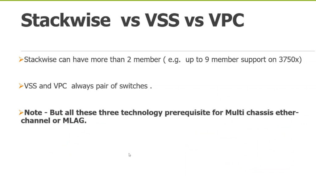
MLAG vs. Stacking vs. LACP
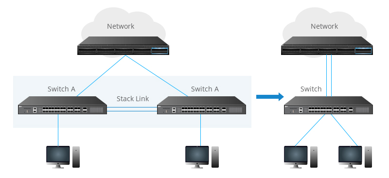
Link aggregation and stacking are common approaches to bundle multiple network connections in one logical link. Compared to conventional connections, these methods are best described as scalable solutions that can provide higher availability, higher reliability and higher bandwidth. MLAG vs. stacking vs. LACP is often asked to define the differences, so this article intends to give an informed explanation of MLAG, LACP, stacking, and the different application scenarios.
Understanding MLAG, LACP, and Stacking
MLAG (Multi-chassis Link Aggregation Group): a non-standard protocol, that implements link aggregation among multiple devices. The devices at both ends of the MLAG send MLAG negotiation packets through the peer-link. The main purpose of MLAG is to deliver system-level redundancy in the event one of the chassis fails.
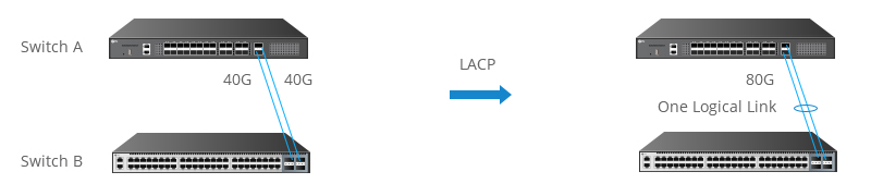
LACP (Link Aggregation Control Protocol): a subcomponent of IEEE 802.3ad standard, provides a method to control the bundling of several physical ports together to form a single logical channel. LACP allows a network device to negotiate an automatic bundling of links by sending LACP packets to the peer. For more basics, Understanding Link Aggregation Control Protocol will give you the answer.