- 8777701917
- info@saikatinfotech.com
- Basirhat W.B

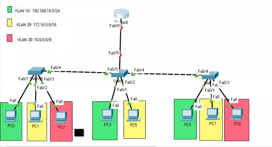
Inter-VLAN (Virtual Local Area Network) refers to the communication between different VLANs within a network. VLANs are used to segment a network into smaller, isolated broadcast domains. By default, devices in different VLANs cannot communicate with each other directly because they are separated logically.
However, Inter-VLAN routing allows traffic to flow between these isolated VLANs. This can be achieved by using a router or a Layer 3 switch that supports routing between VLANs. Here’s how it typically works:
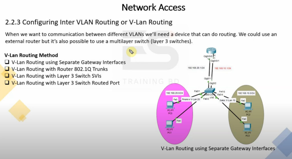
Router or Layer 3 Switch: A Layer 3 device, such as a router or a Layer 3 switch, is used to perform routing between the VLANs. The device will have interfaces configured for each VLAN (often called sub-interfaces) to handle the traffic.
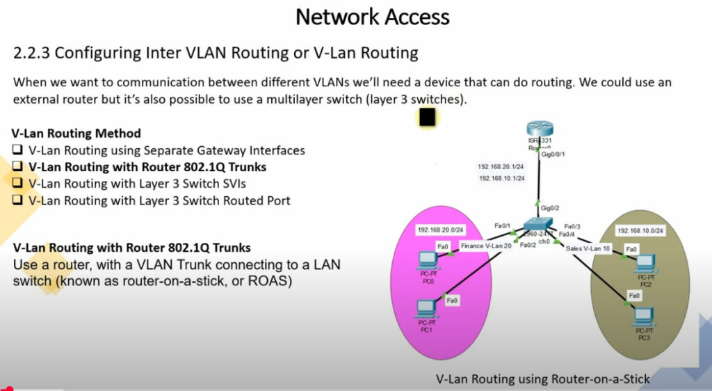
Router-on-a-stick: This is a common technique where a single physical interface on a router is used for routing between multiple VLANs. The router uses sub-interfaces, each with its own IP address corresponding to the VLAN’s subnet.
Layer 3 Switch: If you have a Layer 3 switch, it can perform inter-VLAN routing without needing an external router. These switches operate at both Layer 2 and Layer 3 of the OSI model and are capable of routing traffic between VLANs directly.
In summary, Inter-VLAN routing enables different VLANs to communicate with each other, typically using a router or Layer 3 switch, and is a key part of managing network segmentation in larger networks.

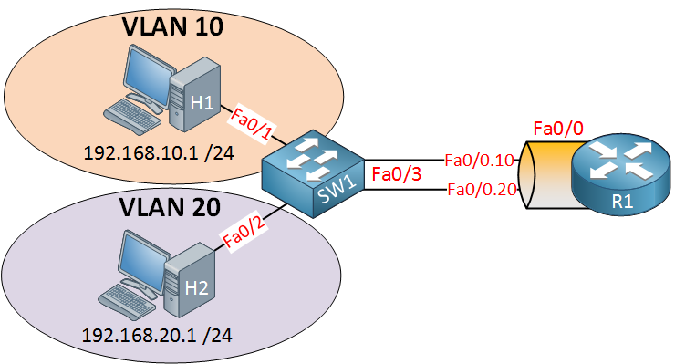
In this lesson, we are going to take a look at routing between VLANs. When we want communication between different VLANs, we’ll need a device that can do routing. We could use an external router, but it’s also possible to use a multilayer switch (aka layer three switches).
SW1(config)#interface fa0/3
SW1(config-if)#switchport trunk encapsulation dot1q
SW1(config-if)#switchport mode trunk
SW1(config-if)#switchport trunk allowed vlan 10,20
This is how we configure SW1. Make interface fa0/3 a trunk port, and for security measures, I made sure that only VLAN 10 and 20 are allowed. Let’s create two sub-interfaces and assign the correct VLANs:
R1(config)#interface fa0/0.10
R1(config-subif)#encapsulation dot1Q 10
R1(config-subif)#ip address 192.168.10.254 255.255.255.0
R1(config)#interface fa0/0.20
R1(config-subif)#encapsulation dot1Q 20
R1(config-subif)#ip address 192.168.20.254 255.255.255.0
Don’t forget to add an IP address for each VLAN. Here’s what the routing table looks like:
R1#show ip route

Codes: C - connected, S - static, R - RIP, M - mobile, B - BGP
       D - EIGRP, EX - EIGRP external, O - OSPF, IA - OSPF inter area
       N1 - OSPF NSSA external type 1, N2 - OSPF NSSA external type 2
       E1 - OSPF external type 1, E2 - OSPF external type 2
       i - IS-IS, su - IS-IS summary, L1 - IS-IS level-1, L2 - IS-IS level-2
       ia - IS-IS inter area, * - candidate default, U - per-user static route
       o - ODR, P - periodic downloaded static route

Gateway of last resort is not set

C    192.168.10.0/24 is directly connected, FastEthernet0/0.10
C    192.168.20.0/24 is directly connected, FastEthernet0/0.20
What is SVI?
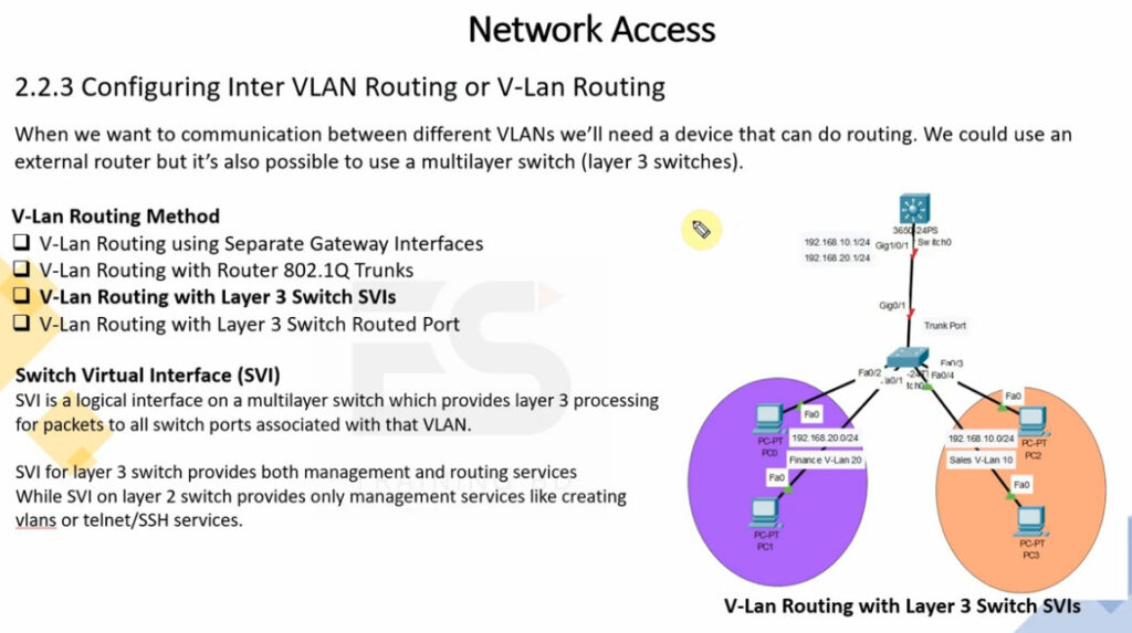
An SVI (Switched Virtual Interface) is a virtual interface on a Layer 3 switch used to provide Layer 3 (IP) functionality to a VLAN on a network. It allows the switch to perform routing functions for that VLAN. Essentially, an SVI acts as the default gateway for all devices in the VLAN it is associated with.
Here are key points about an SVI:
Layer 3 Interface: Although VLANs are typically associated with Layer 2 (data link layer) functionality, the SVI allows a Layer 3 switch to route traffic between VLANs. This provides IP routing capabilities for each VLAN.
VLAN and IP Address: Each SVI is associated with a specific VLAN and typically has an IP address configured on it. Devices within that VLAN will use the SVI’s IP address as their default gateway, allowing them to communicate with devices outside of their VLAN.
No Physical Interface: Unlike traditional interfaces on routers or Layer 2 switches, an SVI does not correspond to a physical interface. It’s purely virtual and exists in software on the switch.
Routing Between VLANs: When you configure an SVI, it enables the Layer 3 switch to perform routing between multiple VLANs. This is known as inter-VLAN routing.
For example, if you have two VLANs (VLAN 10 and VLAN 20), you could configure an SVI for each VLAN on a Layer 3 switch:
192.168.10.1.192.168.20.1.These IP addresses would serve as the default gateways for devices in VLAN 10 and VLAN 20. Traffic between VLANs would be routed by the switch via the SVIs.
Key Benefits of SVIs:
Efficient Routing: SVIs provide a quick and efficient method of routing traffic between VLANs without needing an external router.
Simplified Configuration: On Layer 3 switches, SVIs make it easy to implement inter-VLAN routing with minimal hardware.
Scalability: You can have multiple SVIs on a single Layer 3 switch, making it scalable for larger networks with many VLANs.
In summary, an SVI allows a Layer 3 switch to route traffic between VLANs, acting as a gateway for each VLAN while remaining a virtual (non-physical) interface.
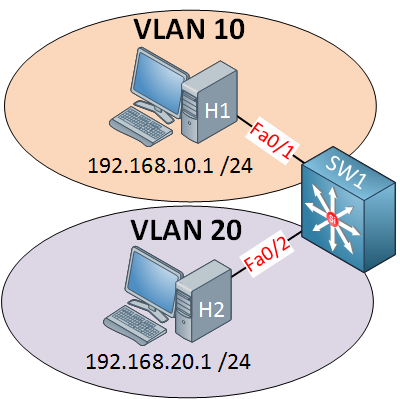
This is the picture of a multilayer switch. This switch has routing capabilities! I can configure something called an SVI (Switch Virtual Interface) for each VLAN and put an IP address on it. This IP address can be used for computers as their default gateway. Here’s how to configure it:
SW1(config)#ip routing
SW1(config)#interface vlan 10
SW1(config-if)#no shutdown
SW1(config-if)#ip address 192.168.10.254 255.255.255.0
SW1(config)#interface vlan 20
SW1(config-if)#no shutdown
SW1(config-if)#ip address 192.168.20.254 255.255.255.0