- 8777701917
- info@saikatinfotech.com
- Basirhat W.B

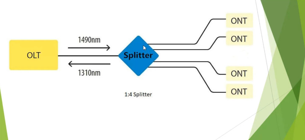
A fiber optic splitter is a passive optical device used in fiber optic networks to divide a single input signal into multiple output signals or combine multiple input signals into a single output. Splitters are commonly used in Passive Optical Networks (PONs), Fiber-to-the-Home (FTTH) deployments, CATV (cable television), and other optical communication systems.
There are different types of fiber optic splitters, and they can be classified based on various factors, including construction method, configuration, and functionality. Below is a comprehensive list of the main types of fiber optic splitters:
| Type | Description | Advantages | Disadvantages | Applications |
|---|---|---|---|---|
| FBT Splitters | Fused biconical tapering of fibers. | Low cost, widely available. | Higher insertion loss, limited bandwidth. | FTTH, PON, CATV, low-to-medium split ratios. |
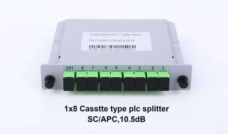
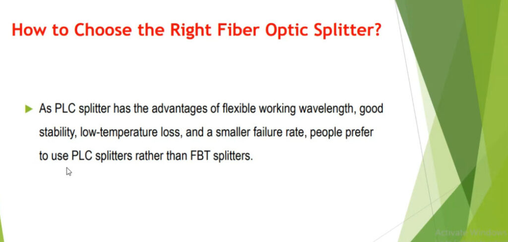
| PLC Splitters | Planar lightwave circuit splitters. | Low insertion loss, high reliability, wide split ratios. | Higher cost, larger size. | High-density networks (FTTH, GPON, data centers). |
| Star Couplers | Central point where fibers are split. | Simple construction, low cost. | Limited scalability. | Short-distance, low-medium splitting ratios. |
| Tapered Splitters | Light is split through a tapered fiber. | Low cost, compact design. | Higher insertion loss at large split ratios. | Low-to-medium split ratios in telecom. |
| Adaptive Splitters | Split ratio adjusts dynamically based on needs. | Flexible and reconfigurable. | Complex and expensive. | Dynamic or reconfigurable optical networks. |
| WDM Splitters | Used in WDM systems to split signals by wavelength. | High capacity, multiple signals on the same fiber. | Complex and higher cost. | DWDM systems, high-capacity networks. |
| Variable Optical Splitters | Split ratio can be adjusted as needed. | Flexible, adaptable to different conditions. | Expensive, complex. | Testing, dynamic networks, PONs. |
The choice of fiber optic splitter depends on the network requirements, including split ratio, distance, signal loss, and cost considerations. FBT splitters are often used for low-to-medium split ratios, while PLC splitters are preferred for high-density, long-range applications due to their low loss and reliability. Adaptive and variable splitters offer flexibility in dynamic networks, while WDM splitters are essential for high-capacity systems like DWDM.
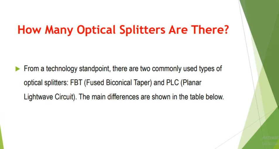
Optical fiber cables have deeply influenced telecommunication and how data are transmitted. The optical splitter is a crucial part of the fiber optic passive network system. It is an optical fiber tandem equipment connected to the input fiber, and it splits and conducts the optical signals into multiple output pathways. There are mainly two technologies for manufacturing optical splitters, according to which we can divide the optical splitters into two types: fused biconical taper splitter (FBT splitter) and planar lightwave circuit splitter (PLC splitter). Each type of optical splitter has its advantages and disadvantages. But do you know the differences between FBT and PLC splitters and how to choose a suitable one?
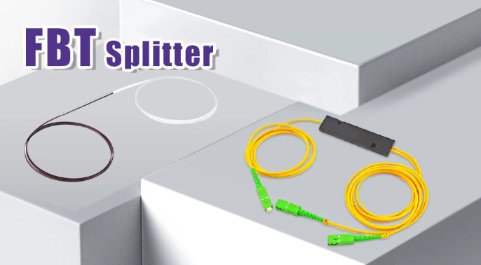
The FBT splitter is a primary optical splitter. Not only does it use cheap and easily available raw materials, but it also holds a manufacturing process simple and threshold-free. An FBT splitter undergoes the following steps during its production:
The uncomplicated flow of production allows this type of optical splitter to be widely applied. But this rough process also makes FBT splitters lack precision, making them suitable primarily for devices with fewer outputs. An FBT splitter over 1×4 will require a combination of several 1×2 structures and an integral package. Steel tube splitter and ABS splitter are two common packaging types for FBT splitter.
Pros:
Cons:
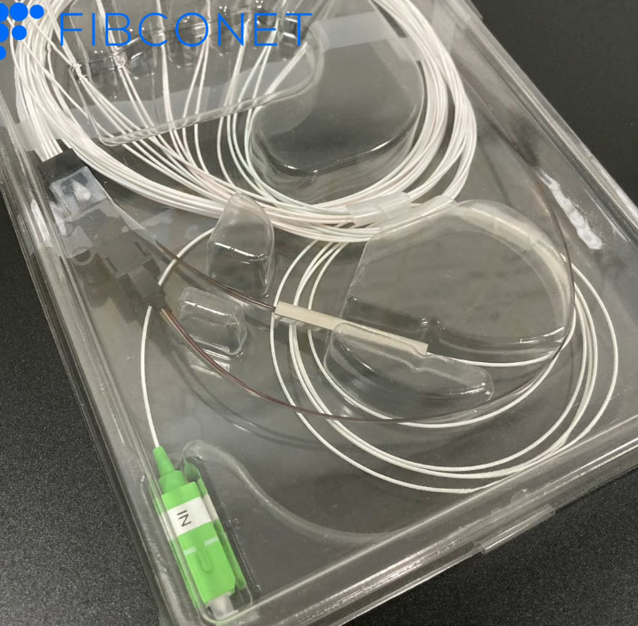
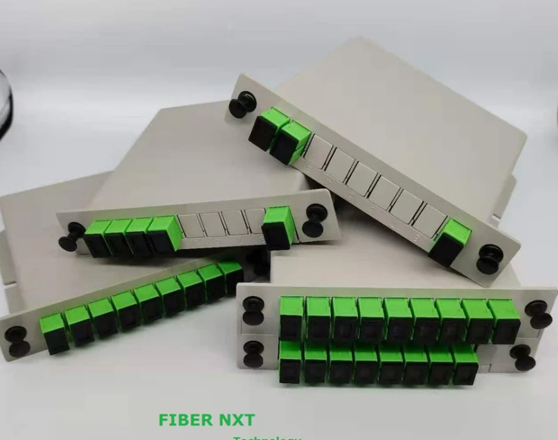
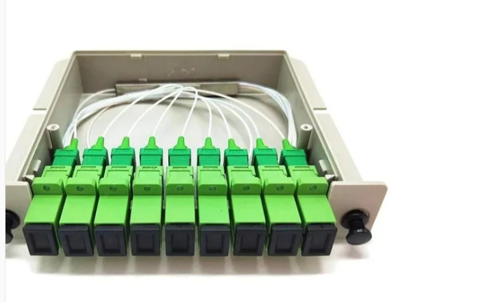
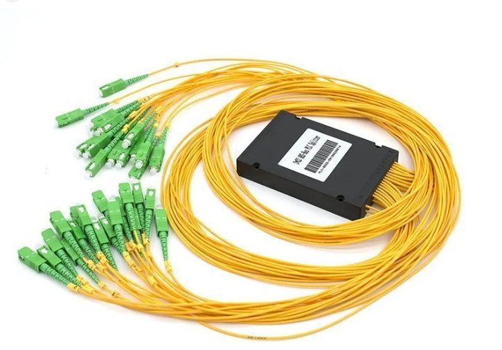
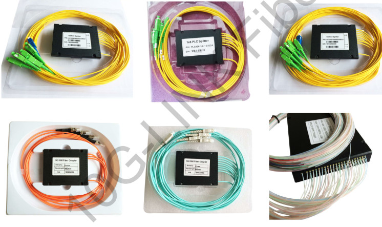
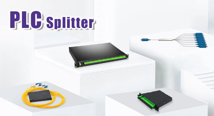
The PLC splitter takes an optical chip containing a lightwave circuit as the core component. The input fiber on the fiber optic link transmits light energy to the chip through an optical array coupled to one end of the chip, and the waveguide on the chip plays a role in splitting the optical signals and conducting them to the output fibers through another optical array coupled to the other end of the chip. The introduction of semiconductor chip technology contributes to reducing the size of optical splitters. Moreover, this sophisticated technology has effectively improved the division capacity of such splitters, making the splitting more accurate and even. But this also means that the fabrication process of the PLC optical splitter is more complicated. In terms of packaging way, there are many types of PLC splitters, for example, bare splitter, mini PLC splitter with steel tube or module design, ABS PLC splitter packaged in a plastic box, LGX PLC splitter or cassette splitter packaged in a metal box, rack-mounted PLC splitter designed for 19-inch rack, etc. PLC splitters are preferable in FTTH deployments.
Pros:
Cons:
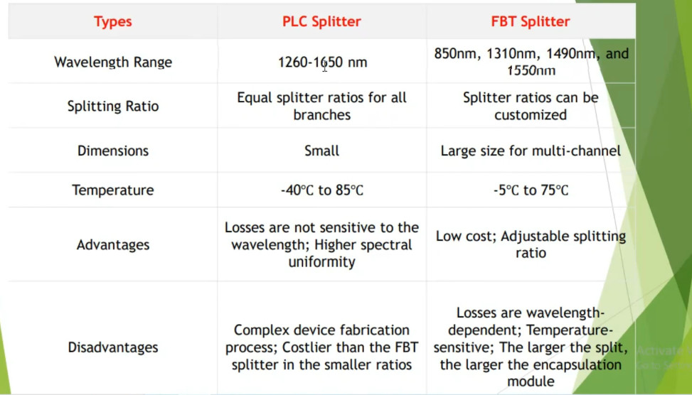
The operating wavelengths supported by the FBT splitter are limited to the following four values but allow a bit of fluctuation: 850 ± 40 nm (custom), 1310 ± 40 nm, 1490 ± 10 nm, and 1550 ± 40 nm. As for the PLC fiber splitter, since the insertion loss remains relatively stable under different wavelengths, its typical operating wavelength spans from 1260 to 1650 nm, encompassing almost all wavelengths required in optical equipment and passive optical network (PON) applications.
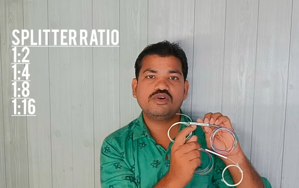
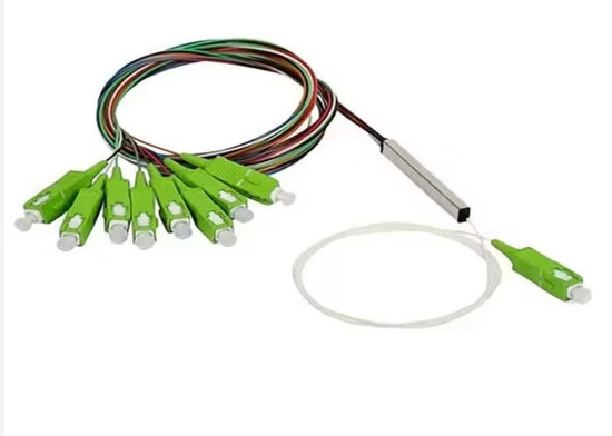
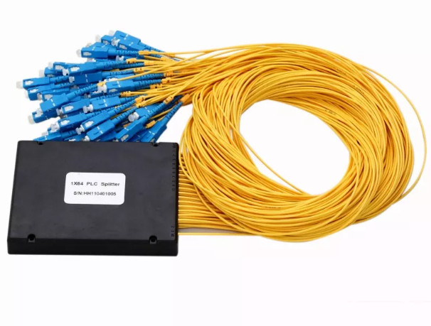
The FBT optical splitter supports a maximum split configuration of 32 channels, offering standard models like 1×2, 2×2, 1×16, alongside specific models like 1×3 and 1×7. In contrast, the PLC splitter can divide light energy into up to 64 portions but only offers standard models such as 1×8, 1×32, 2×64, etc.
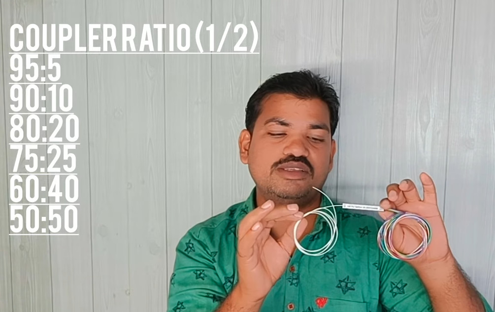
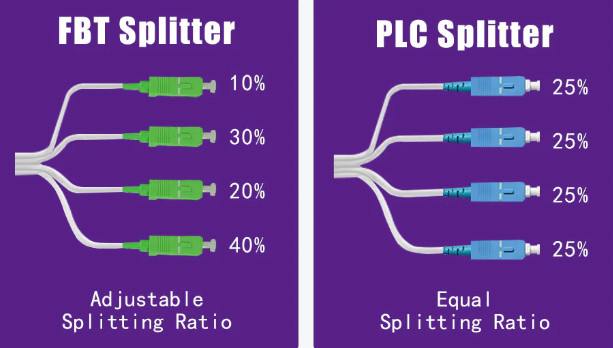
FBT splitters offer flexibility in splitting ratios, especially in scenarios requiring unequal signal distribution. These splitters allow for adjustable splitting ratios depending on the application’s needs, such as 40:60, 30:70, or even 10:90.
In contrast, PLC splitters generally split light equally across all ports, which means that the splitting ratio of a regular 1×2 PLC splitter is 50:50, and a regular 1×4 PLC splitter owns a splitting ratio of 25:25:25:25. In field applications, people sometimes use multiple splitters in cascade to customize the splitting ratio.
FBT splitters with more branches bear a greater risk of failure. Only FBT splitters 1×4 and below are proven to be trustworthy so far. Moreover, making through fusing and tapering optical fibers, the FBT splitters are more prone to inconsistencies and defects. Consequently, they exhibit limited resistance to mechanical shock and vibration. On the other hand, PLC splitters have a lower failure rate and offer higher environmental and mechanical stability. They also guarantee better spectral uniformity thanks to the highly consistent manufacturing.
PLC splitters are friendly to extreme weather conditions, withstanding temperatures ranging from -40℃ to 85℃. But FBT splitters are only applicable for temperatures ranging from -5℃ to 75℃ due to their sensitivity to temperature and poor resistance to thermal expansion and contraction.
High-channel-count FBT splitters require the connection of multiple fiber fusion structures. Besides, the fibers should maintain a certain bending diameter. Therefore, they occupy more physical space and are typically utilized in scenarios where space is not a concern. PLC splitters feature a smaller package size, making them suitable for space-limited applications such as fiber optic patch panels and network terminals.
As for low-channel devices, FBT splitters are cheaper than PLC splitters. However, as the port configurations increase, this price advantage diminishes. It is because, in the production of high-channel equipment, the qualified rate of finished products for FBT splitter decreases, while there is no significant increase in the production cost of PLC splitter. Thus, PLC splitters may be the more cost-effective ones for high-channel devices.
With the rapid spread of FTTX networks, FBT and PLC optical splitters have found their place in PON applications, such as telecommunication, fiber optic local area networks, cable television, optical sensors, measuring instruments, etc. FBT splitters are economical for scenarios with few branches, such as independent data transmission channels and television video networks. While in scenarios that require a wide wavelength range and own plenty of users, such as network convergence systems and FTTH, PLC splitters are more practical. They are also better for broadband transmission or fiber optic communication systems.
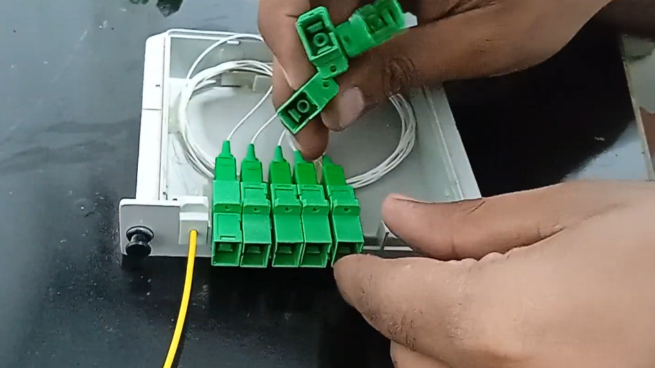
PLC splitters are widely used in passive optical networks to connect service provider endpoints and terminal demarcation devices in front of customer premises wiring. Whether in centralized distribution or distributed access architectures prevalent in fiber-to-the-home (FTTH) deployments, PLC splitters can meet all the needs.
In summary, PLC splitters surpass FBT splitters in terms of benefits. Although FBT splitters may be appropriate for small passive optical LANs, rural FTTX deployments, and specific asymmetric split ratio applications, PLC splitters, known for their superior performance, are better suited for broader fields. You could consider all the factors like wavelength compatibility, splitting ratio, operating environment, available space, and budget before making up your mind.
The light passes through the input fiber array of the PLC splitter and enters the planar lightwave circuit chip. The optical waveguide on the semiconductor chip divides the light into two or more independent signals and guides them to the output fiber array. Finally, the signals are output from different channels.
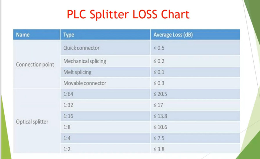
The insertion loss of each output end of an FBT splitter varies greatly. The nominal max uniformity difference of a 1×4 FBT splitter of an equal split is about 1.5 dB, let alone the larger splitters. The poor uniformity affects its overall transmission distance. There is no significant difference in insertion loss at each output terminal of the PLC splitter, making it better for long-distance applications.