- 8777701917
- info@saikatinfotech.com
- Basirhat W.B


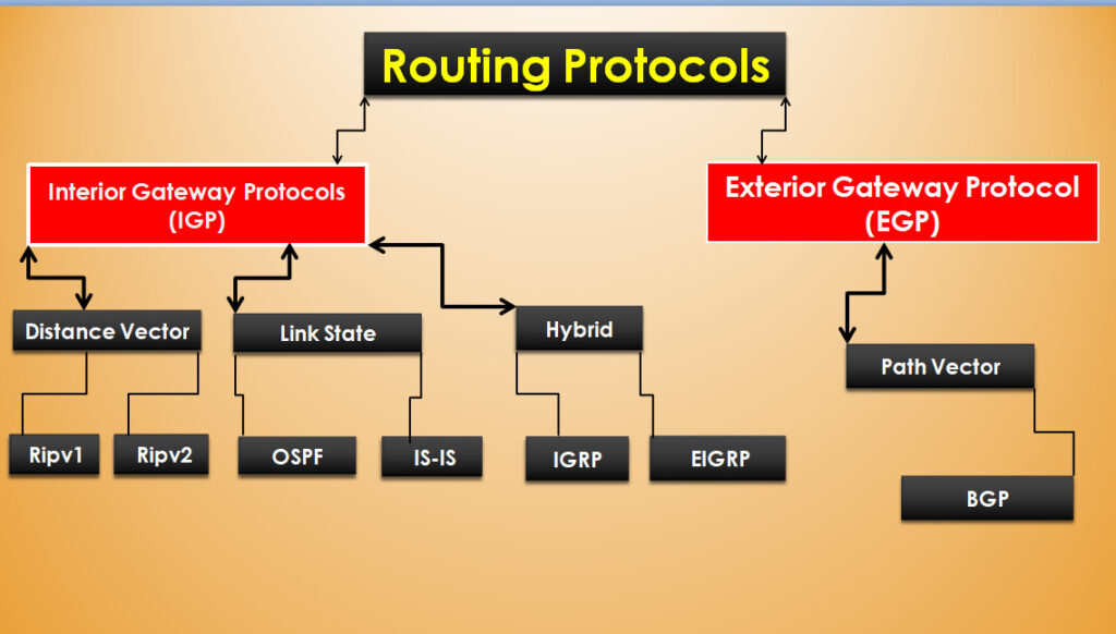


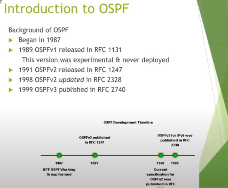
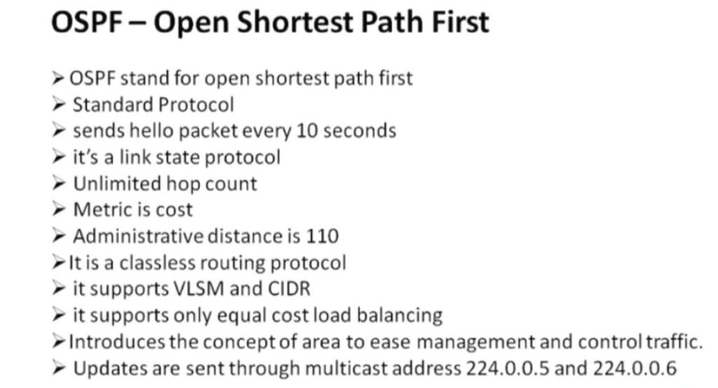
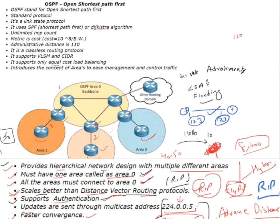
OSPF – Open Shortest path first

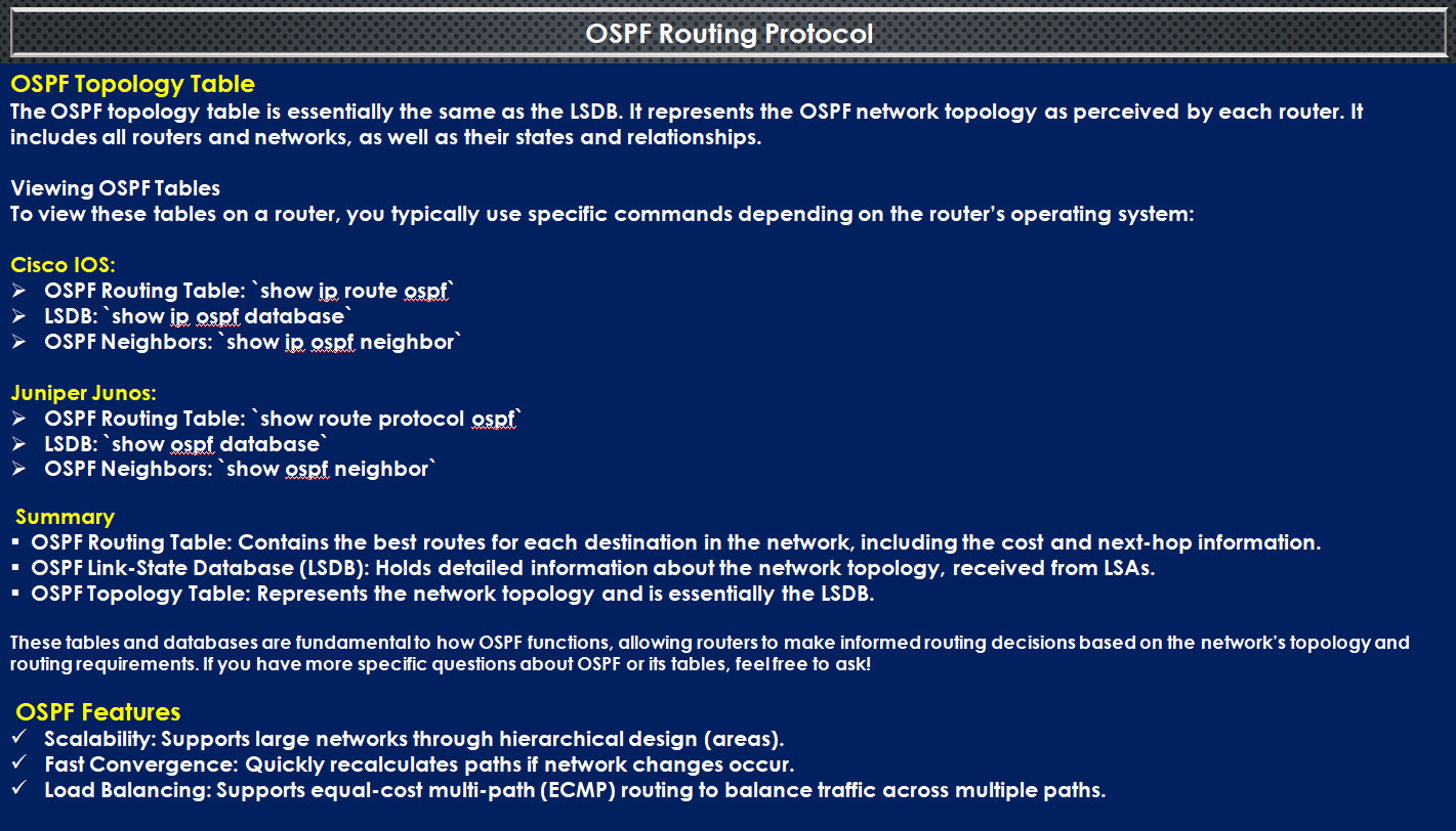
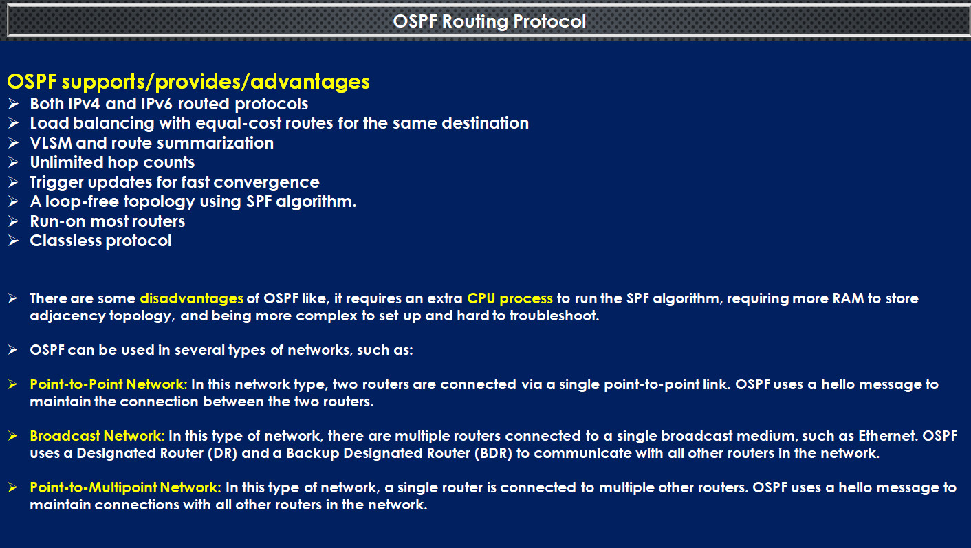
The OSPF protocol supports a couple of cool features such as
Now, let’s explain some of those features.
Open standard protocol: OSPF is not vendor proprietary, and it is deployed by lots of network device vendors such as Cisco, Juniper, Sophos, HP, Dell, Huawei, MikroTik, and more.
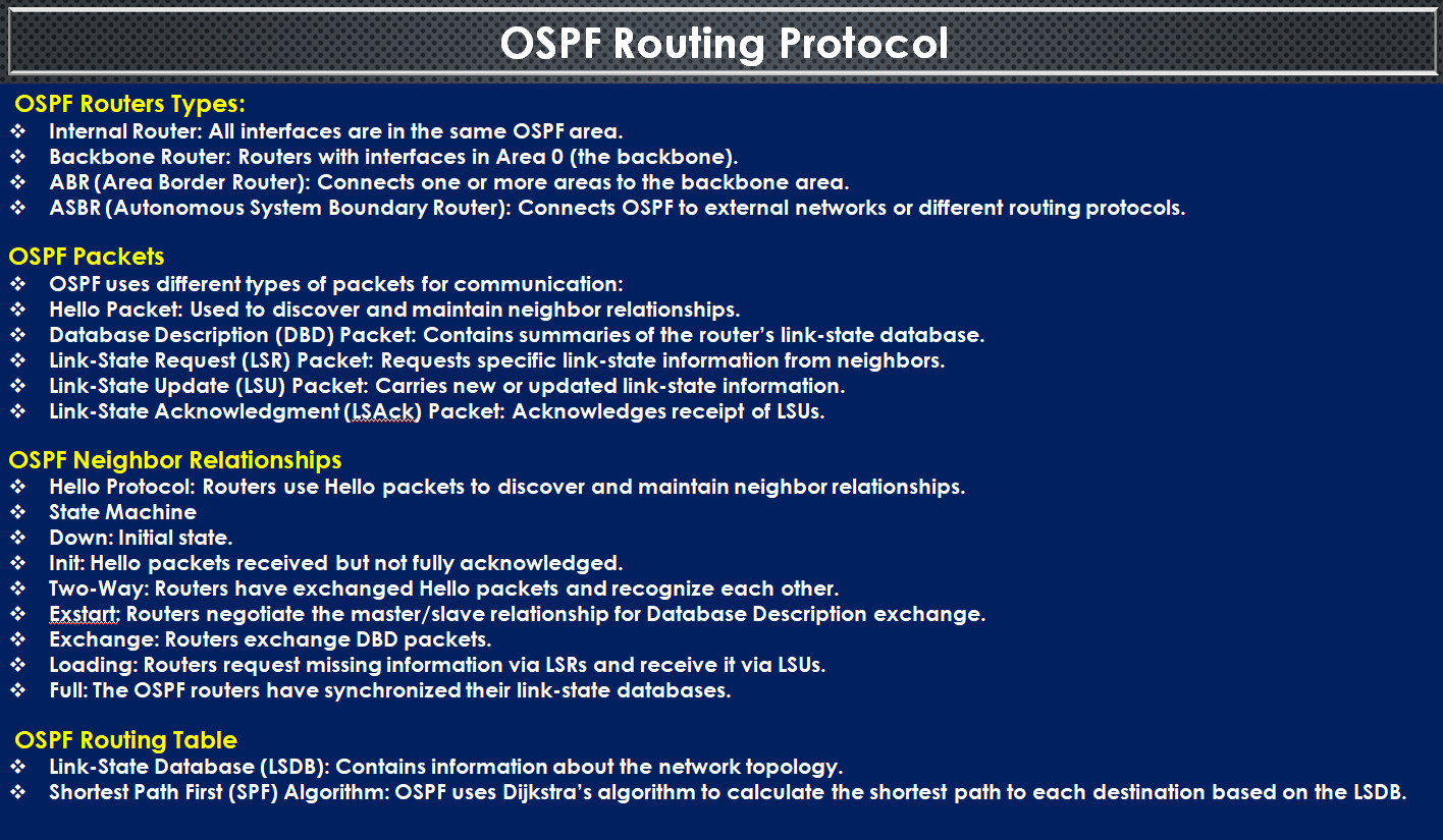
OSPF Packets Types
Full From
What is a HELLO packet?
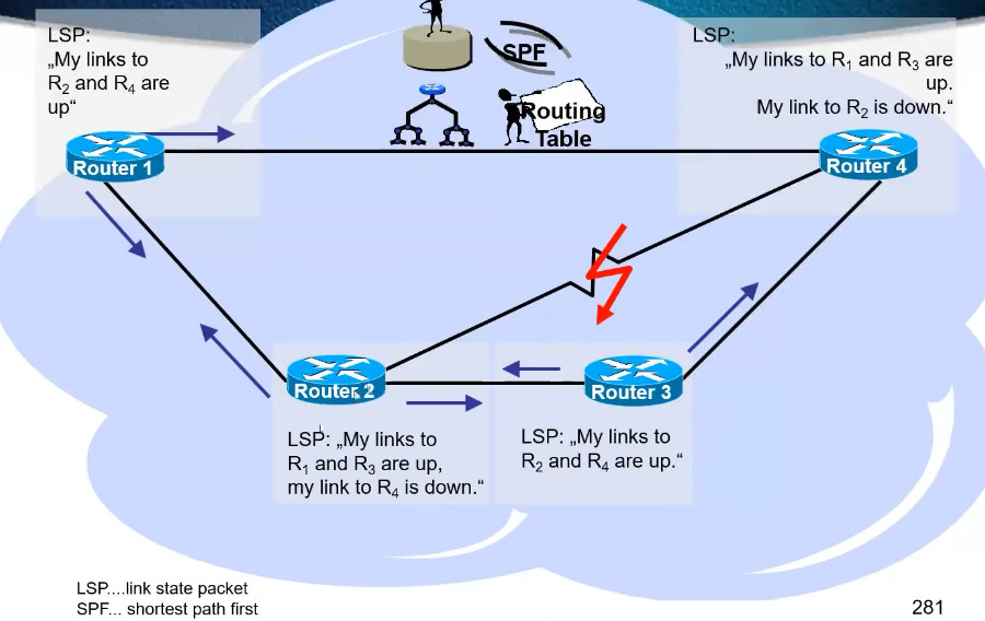
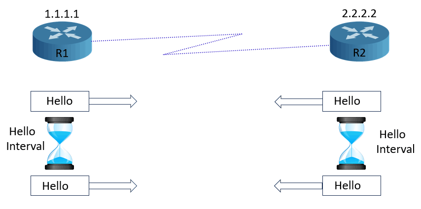
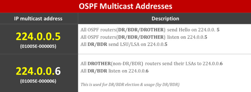
A HELLO packet is a special data packet (message) that is sent out periodically from a router to establish and confirm network adjacency relationships to other routers in the Open Shortest Path First (OSPF) communications protocol. On networks capable of broadcast or Multicast transmission, a HELLO packet can be sent from one router to all other routers simultaneously to discover neighboring routes.
OSPF networks are made up of many interconnected routers. These routers are connected on their interfaces. The HELLO packet is the method for routers to announce to each other that they share an interface.
HELLO packet format and contents
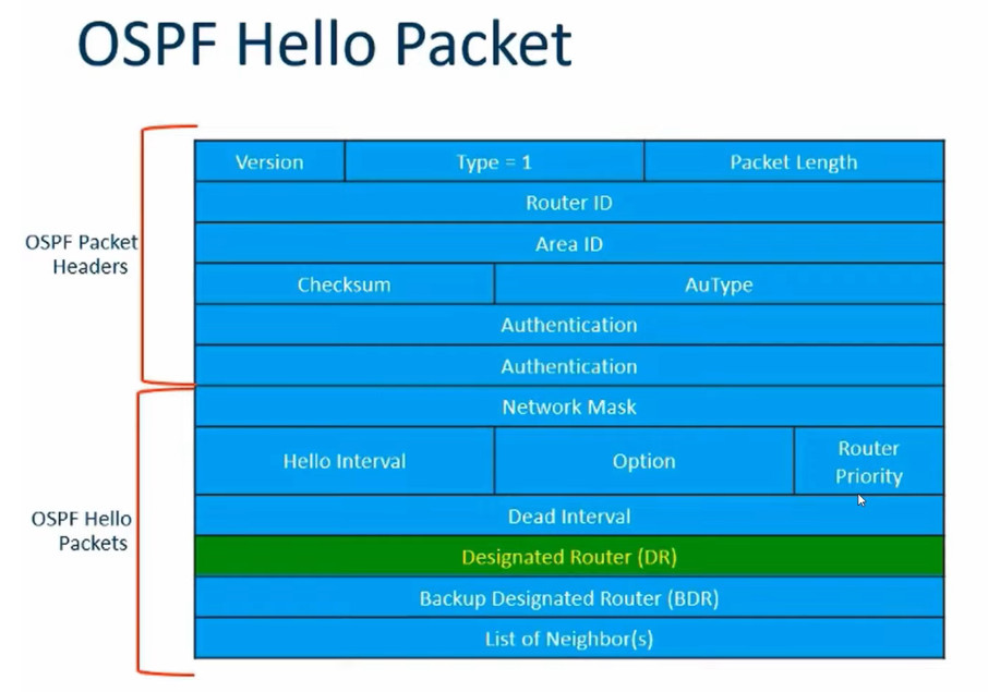
The HELLO packet is made up of the standard OSPF packet header and the HELLO specific information.
What is in the OSPF header?
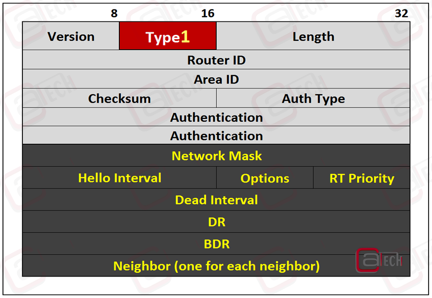
The OSPF packet header contains the OSPF version and packet type, the router ID, area ID, and packet authentication and checksum information:
Type. This identifies the OSPF type of packet: 1 for HELLO packets, 2 for database description, 3 for link state requests, 4 for link state update and 5 to acknowledge other packets have been received.
Router ID. This is a 32-bit number unique to the router to identify it in the OSPF network.
Area ID. This 32-bit number identifies the subarea or logical grouping of neighbor routers in the larger OSPF network.
Authentication. Each OSPF packet may contain authentication information to prevent rouge routers from participating in the network. The authentication can be set to none, simple clear text password, or MD5 hashed password.
What is the HELLO-specific information & Contain Of Hello Packet?
The HELLO packet body contains the network mask, hello interval, router priority, dead interval, designated router, backup designated router and a list of neighbors — the network mask, hello interval and dead interval must be the same for routers to establish adjacency:
Hello Packet Describe Example 2
In OSPF (Open Shortest Path First), a Hello packet is a type of OSPF message used to establish and maintain neighbor relationships between routers. It is an essential part of the OSPF neighbor discovery process.
Here are the key functions and features of the Hello packet in OSPF:
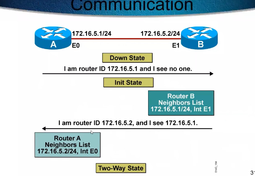
Neighbor Discovery: Hello packets are exchanged between OSPF routers on a common network to discover and identify each other. Once neighbors are discovered, OSPF routers can establish a relationship and start sharing routing information.
Authentication: OSPF Hello packets include an optional authentication mechanism to ensure that the communication between routers is secure.
Hello Interval: The Hello packet includes a Hello Interval, which determines how often Hello packets are sent. This interval is used to check if a neighbor is still reachable.
Router Priority: A field in the Hello packet indicates the router’s priority, which is used in OSPF Designated Router (DR) and Backup Designated Router (BDR) election processes.
Network Mask: The Hello packet includes the network mask of the interface, which helps determine if the two routers are on the same subnet.
Router IDs: The Hello packet includes the router ID (RID) of the sending router, which is a unique identifier for each router in an OSPF domain.
Neighbor List: The Hello packet also contains the list of routers that the sending router knows as neighbors.
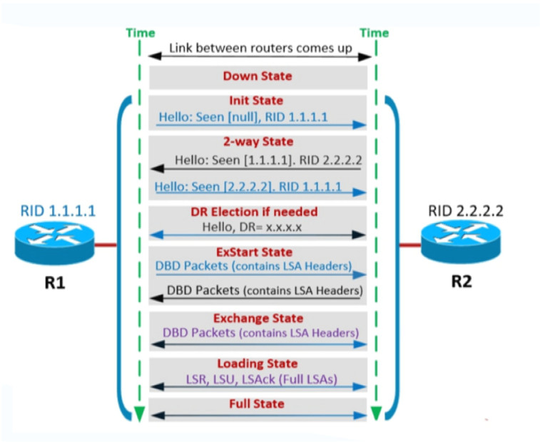
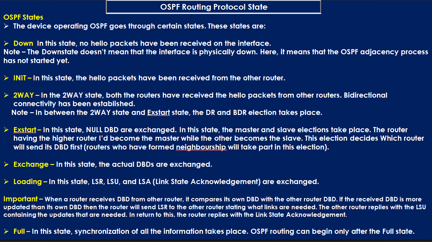
State Machine: The Hello packet is the first packet sent in the OSPF neighbor state machine. The OSPF state machine progresses through various stages (Down, Attempt, Init, Two-Way, Exstart, Exchange, Loading, Full) to establish a full neighbor relationship.
Example of OSPF Hello Packet Format:
In summary, Hello packets are the foundation of OSPF’s neighbor relationship mechanism. They help routers discover each other, maintain neighbor relationships, and facilitate OSPF routing operations.
7 States Of OSPF
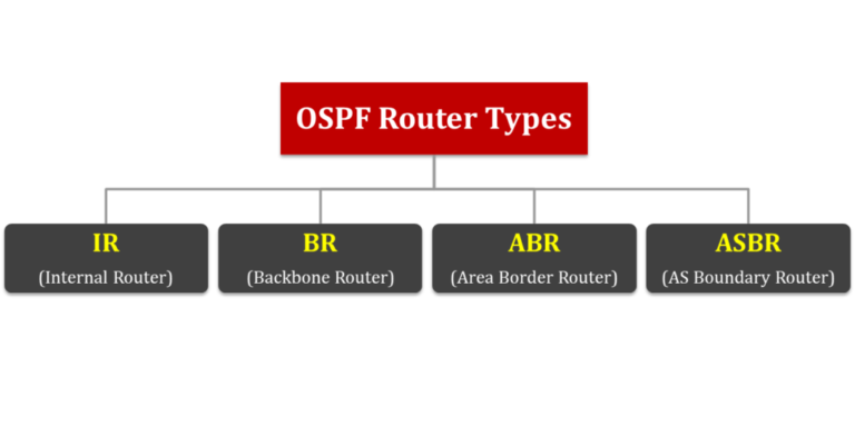
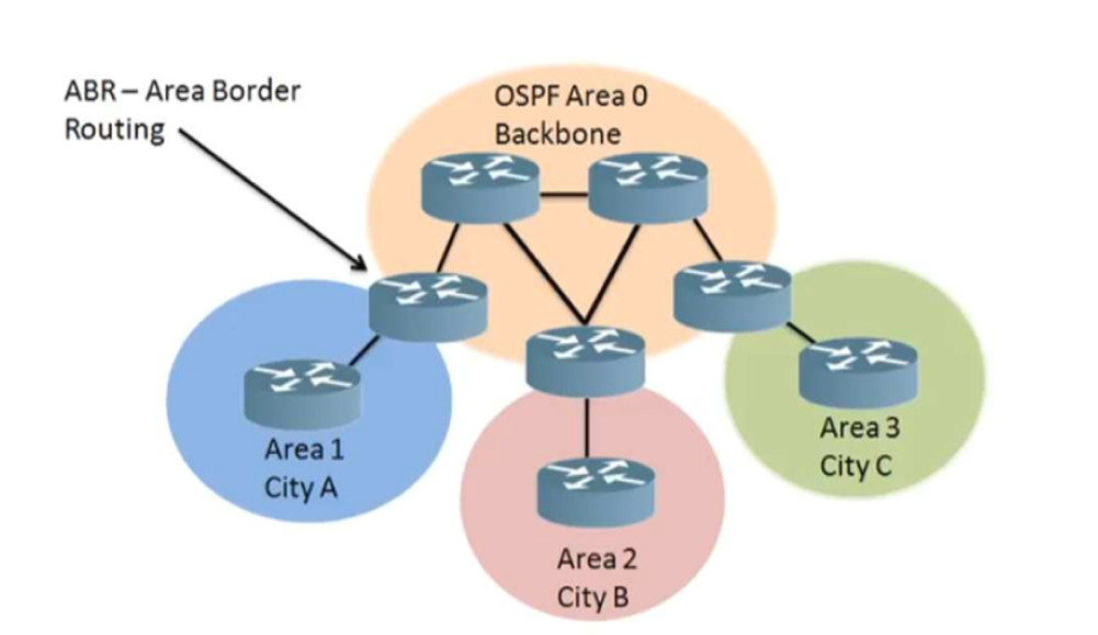
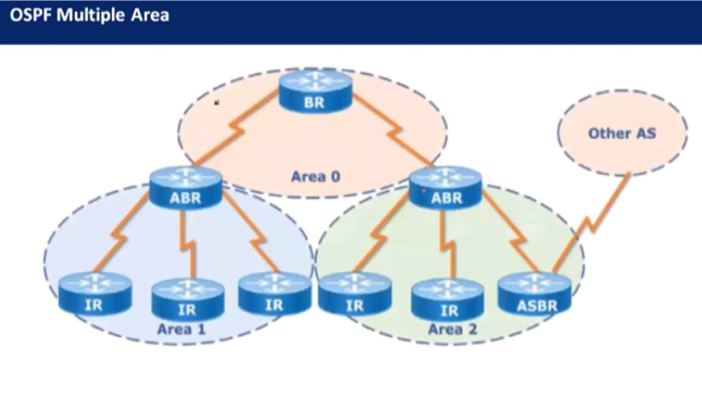
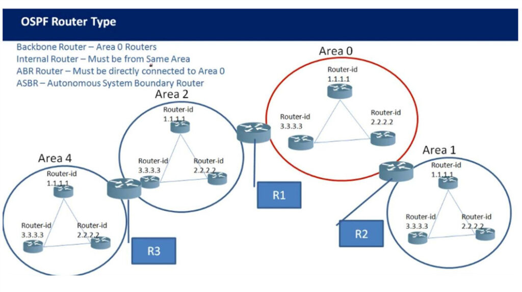
OSPF Router Type
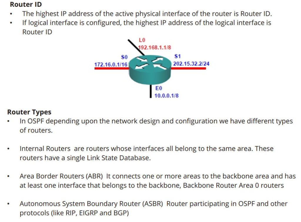
A router with that has OSPF neighbor relationships only with devices in the same area.
A router that has OSPF neighbor relationships with devices in multiple OSPF areas. ABRs gather topology information from their connected areas and distribute it to the backbone area.
A backbone router is a router that runs OSPF and has at least one interface connected to the OSPF backbone area. Since ABRs are always connected to the backbone, they are always classified as backbone routers.
An ASBR is a router that attaches to more than one routing protocol and exchanges routing information between them

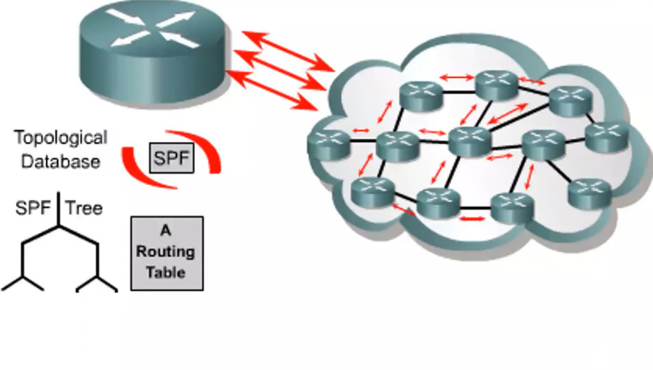
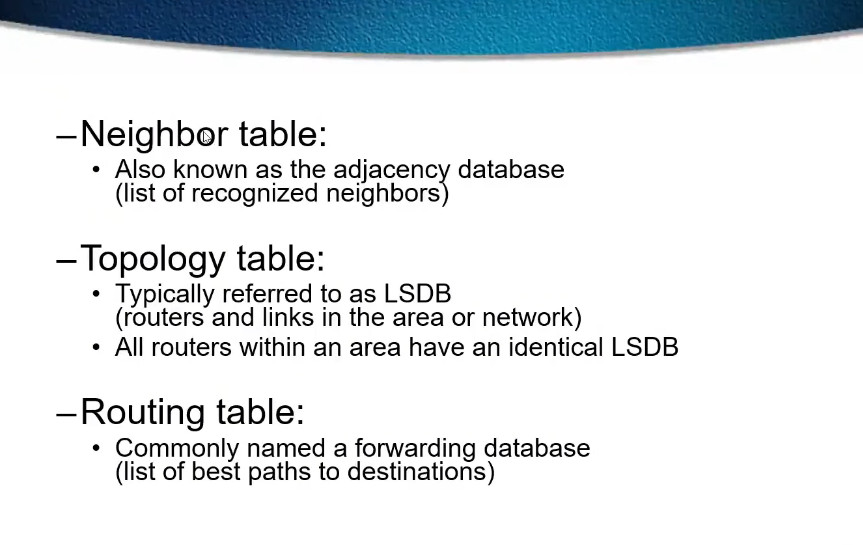
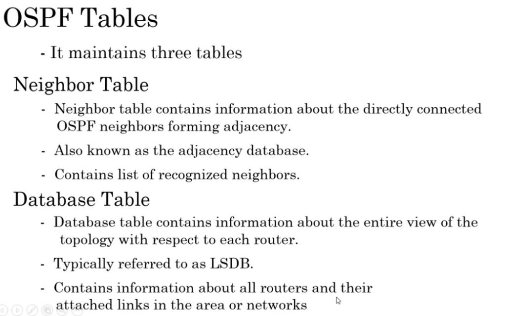
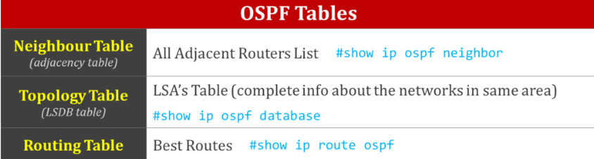
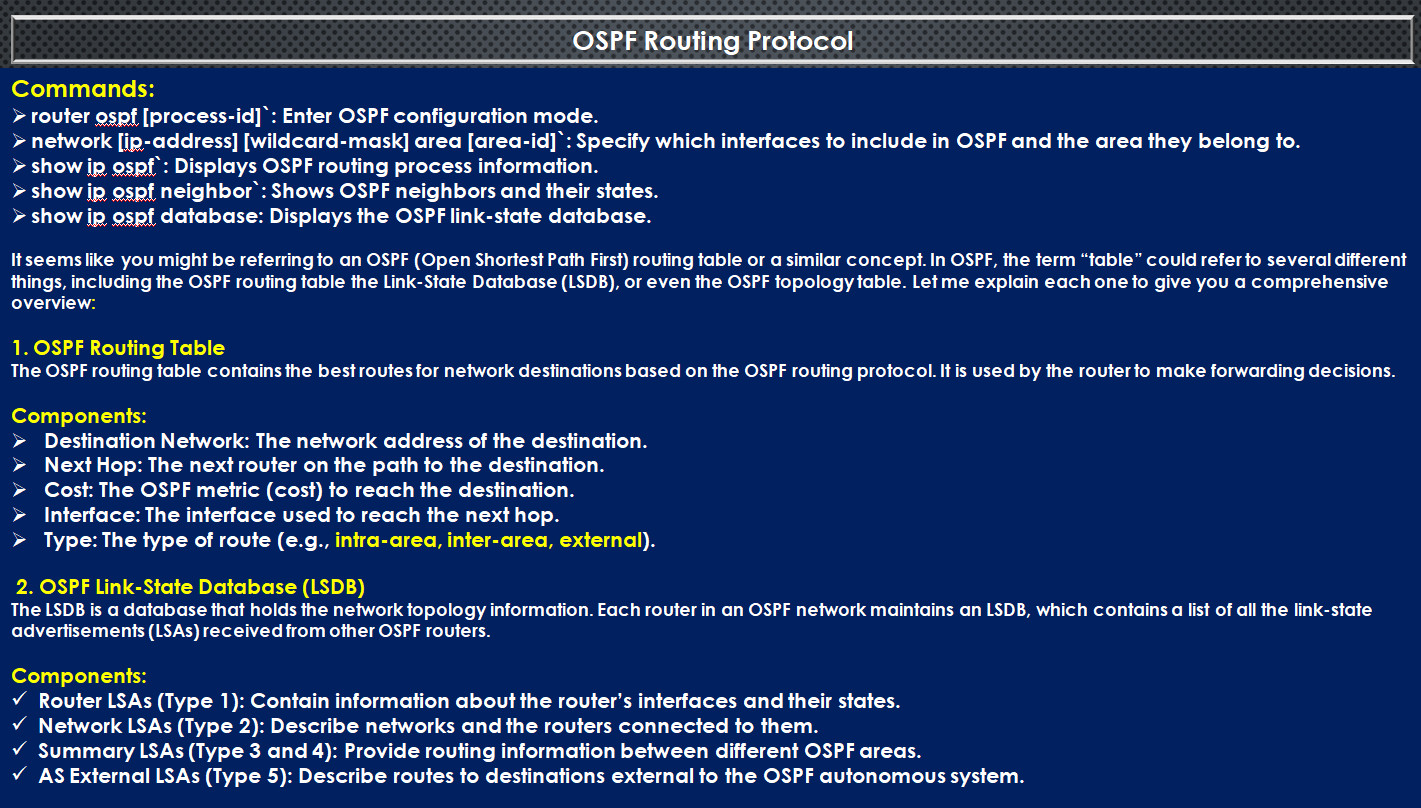
OSPF maintains three tables
Neighbor Table : Neighbor table contains information about the directly connected ospf neighbors forming adjacency
Database table : contains information about the entire view of the topology with respect to each router.
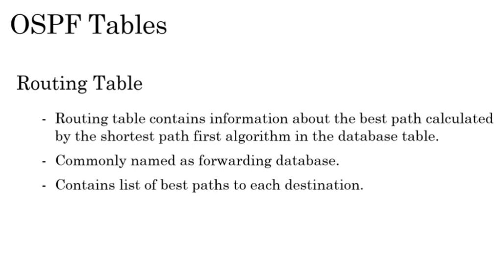
Routing information Table: Routing table contains information about the best path
calculated by the shortest path first algorithm in the database table.
OSPF Advantages & Disadvantages
Advantages of OSPF
Disadvantages
What Neighbor Adjacency Match For Adjacency?
For OSPF (Open Shortest Path First) to form a neighbor relationship (also known as a neighbor adjacency) between two routers, several parameters in the Hello packets must match. If the parameters do not match, the routers will not form a neighbor relationship. The following are the key parameters that must match for OSPF neighbors to establish an adjacency:
If these parameters match between two routers, they will exchange OSPF Hello packets, and the neighbor relationship will be established. If any of these parameters do not match, the routers will not form an adjacency.
The Open Shortest Path First (OSPF) routing protocol supports four different authentication types:
What Type Of OSPF Authentication ?
In OSPF (Open Shortest Path First), authentication is used to ensure that OSPF packets are exchanged only between trusted routers, providing security against unauthorized devices participating in the OSPF routing process.
There are two types of OSPF authentication:
For better security, especially in larger or sensitive environments, MD5 authentication is preferred over plaintext authentication.
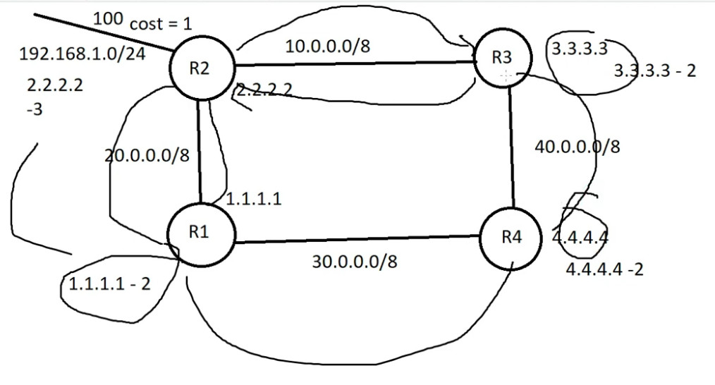
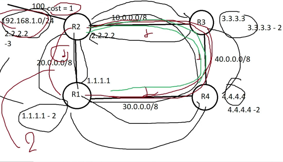
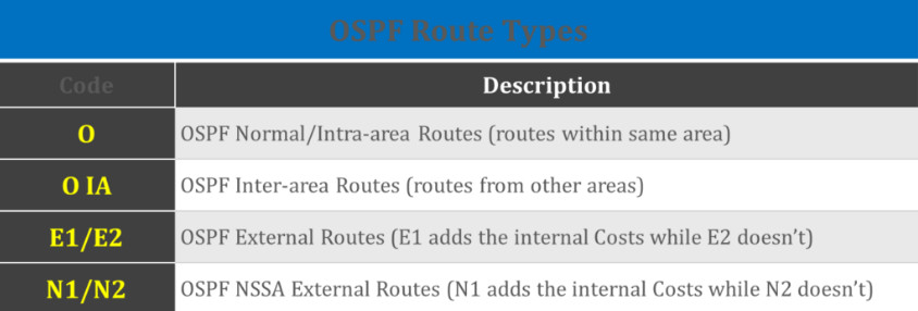
OSPF (Open Shortest Path First) Route Types
OSPF Route Types consists of O, O IA, E1/E2, and N1/N2
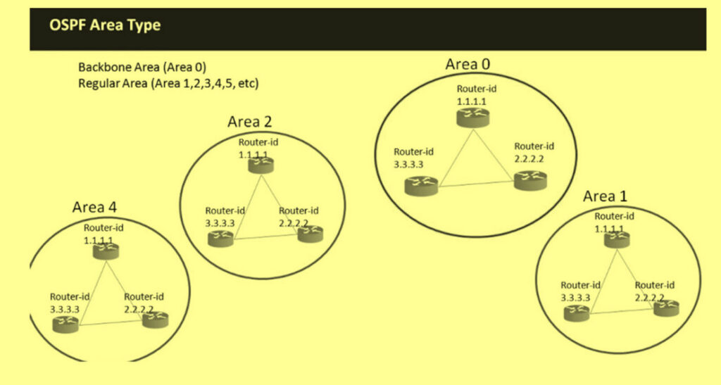
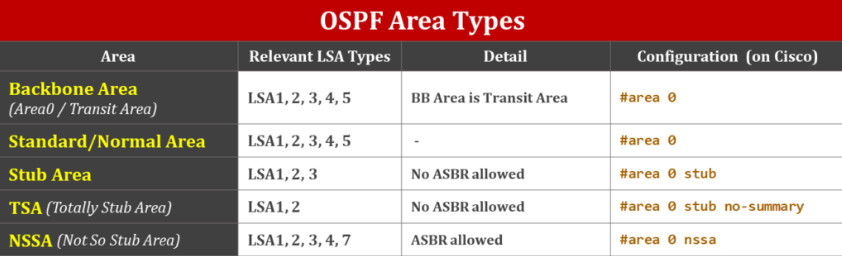
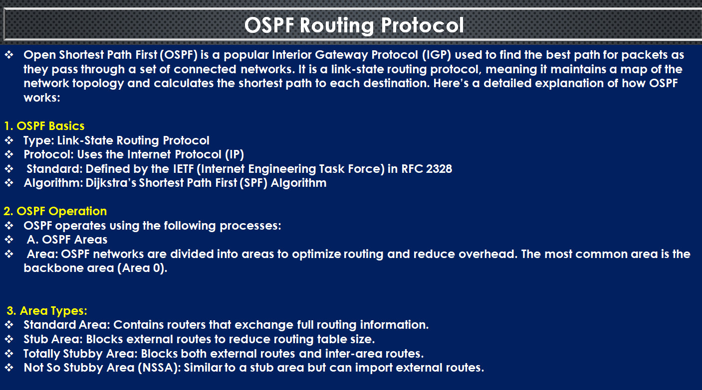
OSPF (Open Shortest Path First) Area Types
There are five types of OSPF Areas: Backbone Area, Standard/Normal Area, Stub Area, TSA (Totally Stub Area), and NSSA (Not So Stub Area)
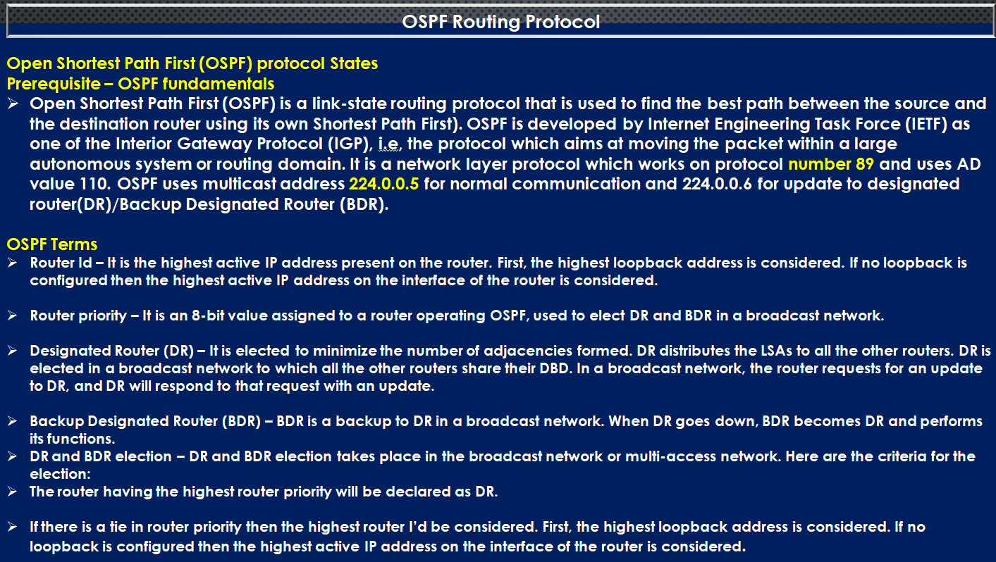
What is Router ID ?
A Router ID (RID) is a unique identifier assigned to a router in a network, used in routing protocols like OSPF (Open Shortest Path First) and BGP (Border Gateway Protocol). The Router ID is essential for network management, troubleshooting, and routing table calculations.

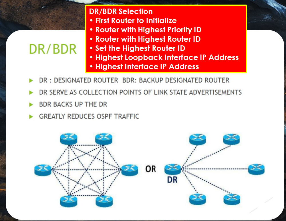
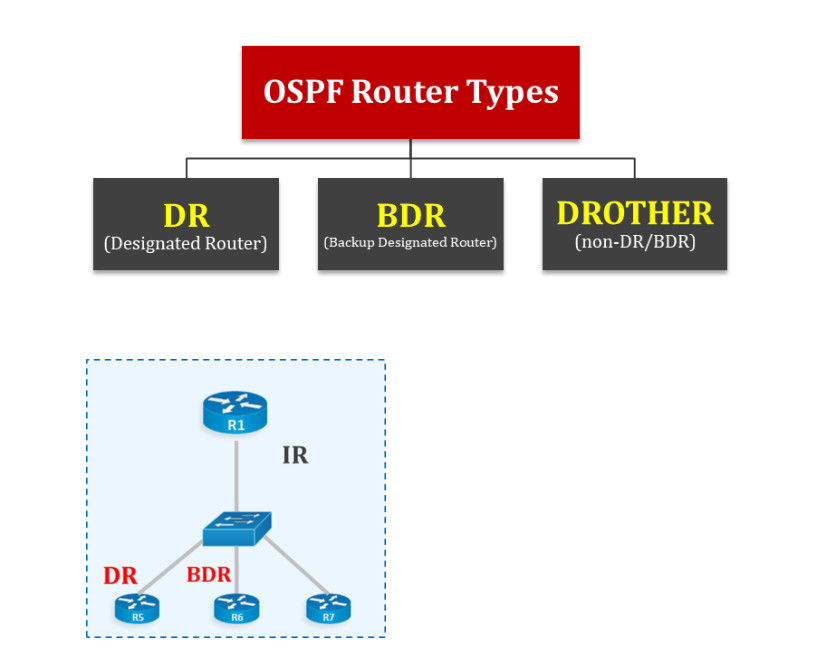
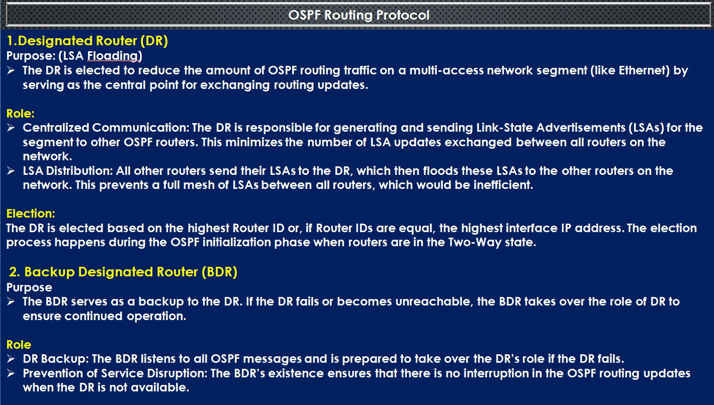
What is DR?
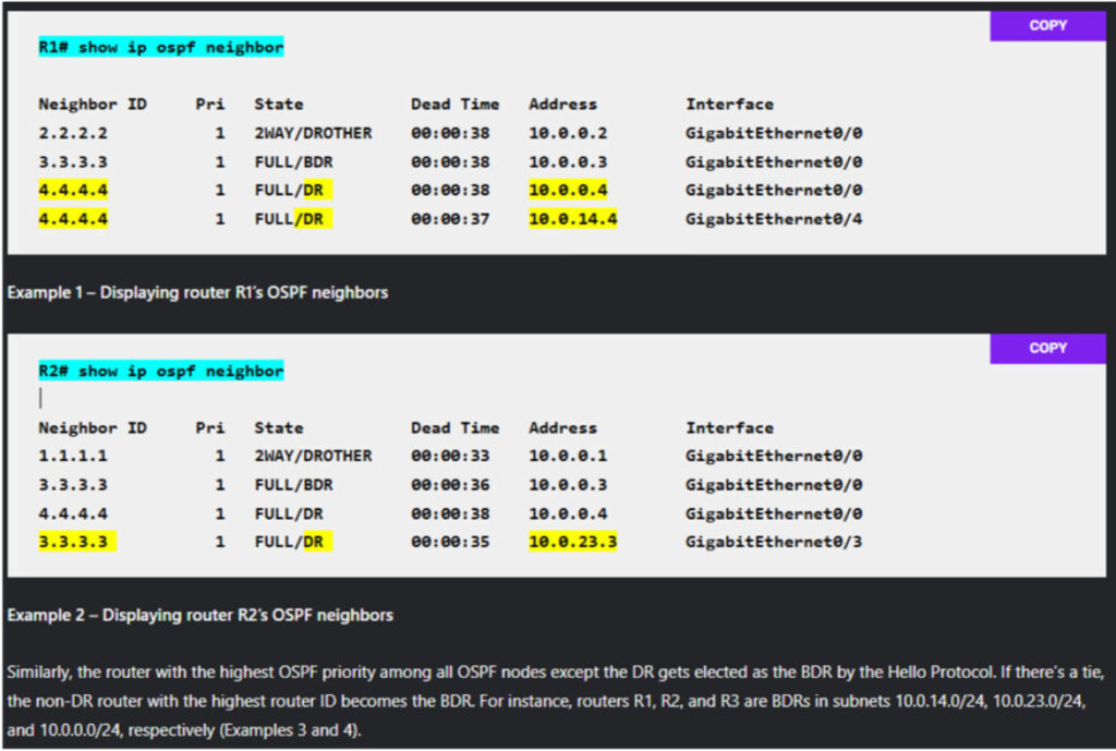
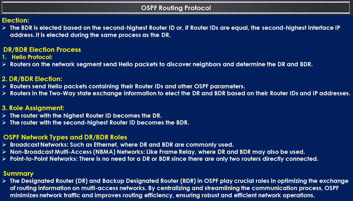
The DR is the Designated Router on a segment, and it is the router with the highest priority among all the segment routers. The priority is a value between zero and 255 that may be configured manually or left at the default value of one. If two or more routers have the same priority, the router with the highest router ID (commonly the highest IP address) turns into the DR. The DR has major functions:
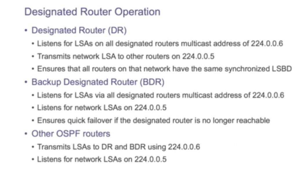
The DR maintains a complete link-state database (LSDB) of the network segment, which contains all of the LSUs received from different routers. The DR additionally generates a network LSA for the network segment, which summarizes the records of all the routers connected to it. The network-LSA is flooded to all different OSPF routers inside the same area.
What is BDR?
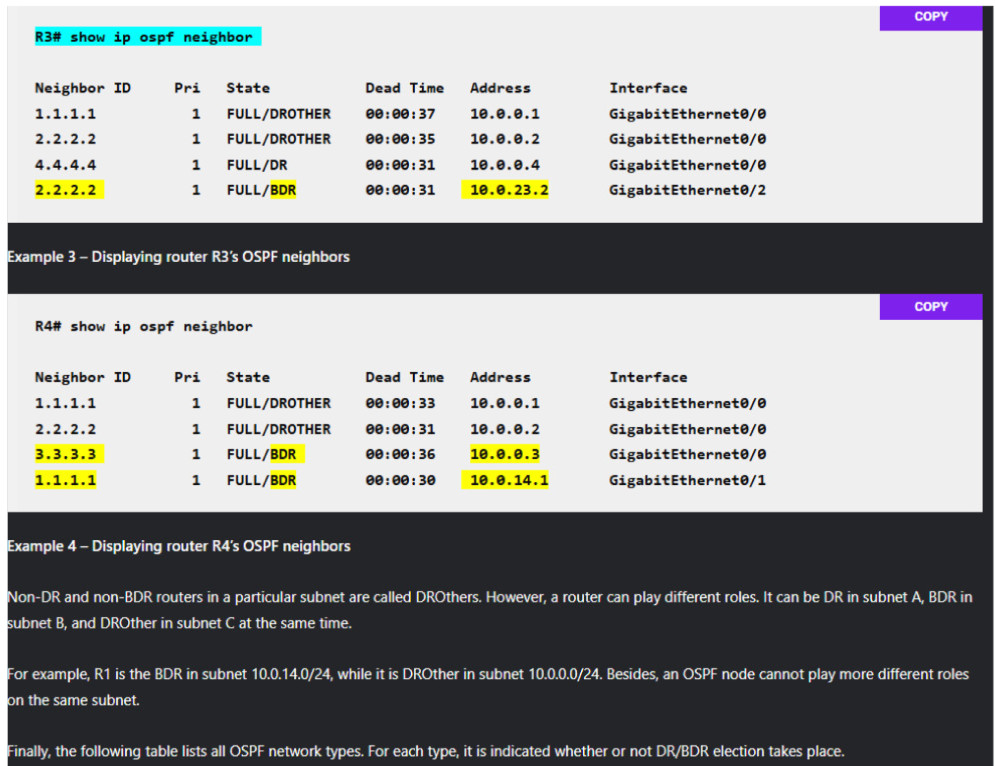
The BDR is the Backup Designated Router on a segment, and it is the router that has the second highest priority amongst all of the routers on the segment and acts as a backup for the DR. The BDR is elected identically as the DR and chosen after the DR. The BDR has two important functions:
The BDR is elected at the same time as the DR, but it does not perform any feature until the DR fails.
Role of DR and BDR
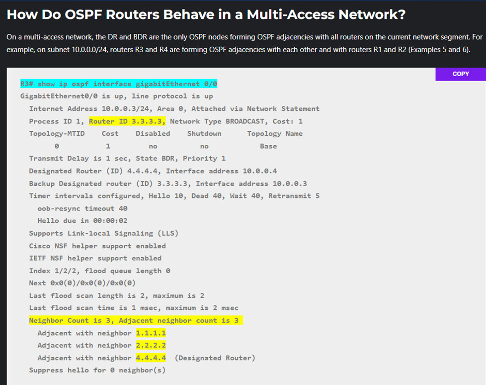
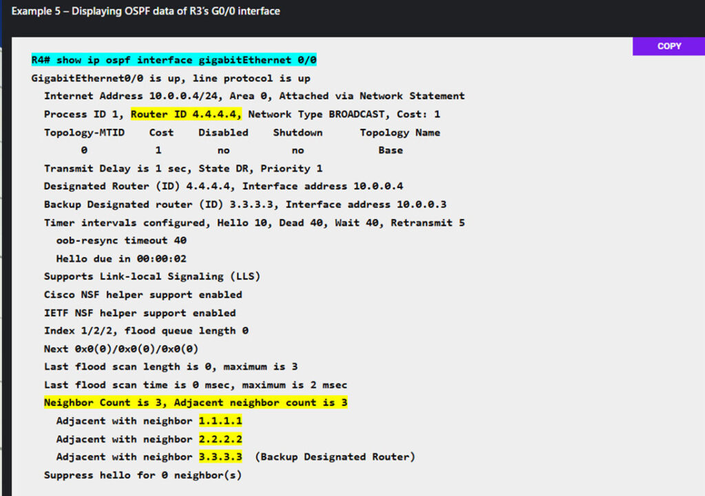
In multi-access network setups (such as Ethernet LANs), routers must maintain an accurate view of the network’s topology. Without a DR and BDR, each OSPF router would have to establish an adjacency with every other OSPF router on the same segment. This would result in an excessive number of adjacencies and significant overhead if LSAs were constantly exchanged.
The DR and BDR simplify this process:
Now that we have a better understanding of DR and BDR in OSPF. Let’s begin with the DR and BDR election process.
DR and BDR election process in OSPF
The DR and BDR election is primarily based on criteria: the OSPF priority and the router ID.
DR and BDR election process in OSPF takes place at some stage in the initialization phase of OSPF whilst routers form adjacencies with every other. The election method follows these steps:
hostname R1

interface GigabitEthernet0/0

ip address 10.0.0.1 255.255.255.0

no shutdown

interface GigabitEthernet0/4

ip address 10.0.14.1 255.255.255.0

no shutdown

router ospf 1

router-id 1.1.1.1

network 10.0.14.1 0.0.0.0 area 0

network 10.0.0.1 0.0.0.0 area 0
hostname R2

interface GigabitEthernet0/0

ip address 10.0.0.2 255.255.255.0

no shutdown

interface GigabitEthernet0/3

ip address 10.0.23.2 255.255.255.0

no shutdown

router ospf 1

router-id 2.2.2.2

network 10.0.23.2 0.0.0.0 area 0

network 10.0.0.2 0.0.0.0 area 0
hostname R3

interface GigabitEthernet0/0

ip address 10.0.0.3 255.255.255.0

no shutdown

interface GigabitEthernet0/2

ip address 10.0.23.3 255.255.255.0

no shutdown

router ospf 1

router-id 3.3.3.3

network 10.0.23.3 0.0.0.0 area 0

network 10.0.0.3 0.0.0.0 area 0
hostname R4

interface GigabitEthernet0/0

ip address 10.0.0.4 255.255.255.0

no shutdown

interface GigabitEthernet0/1

ip address 10.0.14.4 255.255.255.0

no shutdown

router ospf 1

router-id 4.4.4.4

network 10.0.14.4 0.0.0.0 area 0

network 10.0.0.4 0.0.0.0 area 0
Q1. Why is a DR needed for OSPF?
A DR is needed for OSPF to reduce the wide number of adjacencies and LSA flooding in a multi-access network. The DR acts as a central node communication for OSPF routers.
Q2. How does OSPF determine DR and BDR?
OSPF determines the DR and BDR based on priority. The router with the highest priority will be the DR, and the second highest priority will act as BDR. When two routers have the same priority, then router ID comes into action. The router with the highest router ID will be DR.
Q3. What is Dr and ABR in OSPF?
DR stands for designated router, which is mainly used to connect all routers in a network segment. In contrast, ABR, which stands for area border router, is primarily used to connect OSPF areas.
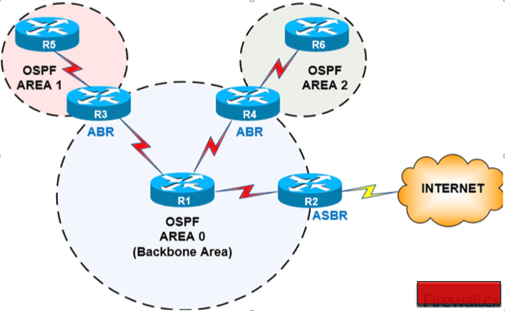
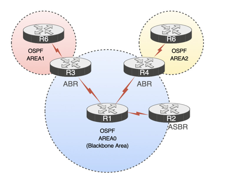
Q4. What is ABR and Asbr in OSPF?
ABR (Area Border Router) connects different OSPF areas to the backbone area (area 0). ASBR (Autonomous System Boundary Router) connects the OSPF network to other routing domains. ABR and ASBR have different roles and functions in OSPF.
Why do we need Designated Routers (DR and BDR)?
OSPF works by forming neighbor adjacencies and exchanging the link-state database between routers. Although the process of forming OSPF neighbors is essential to the protocol, it creates some inefficiencies in shared multiaccess segments such as a traditional Ethernet VLAN.
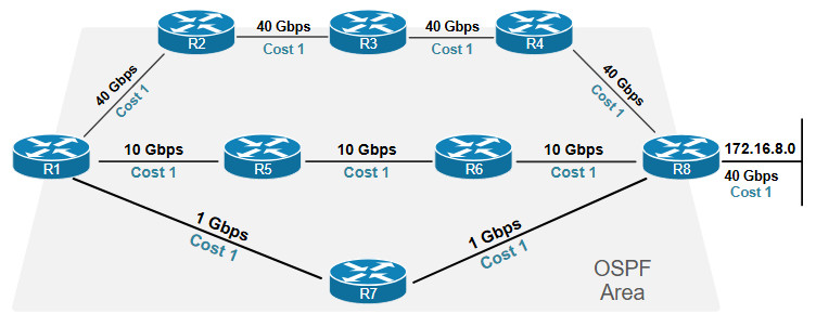
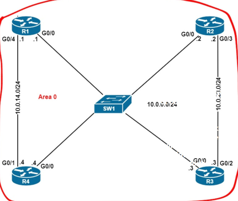
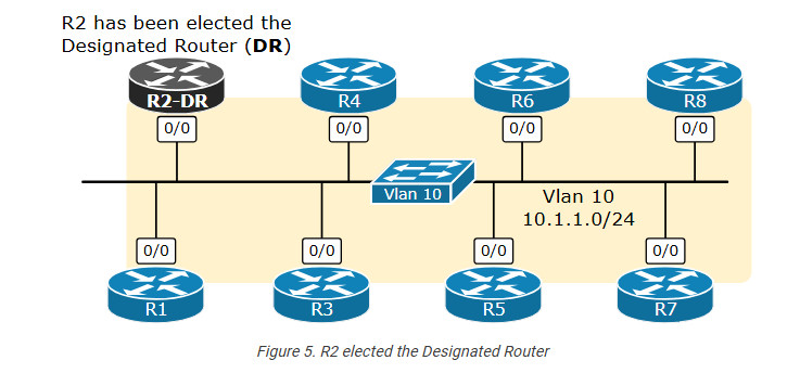
We will use the diagram shown below to explain why we need the concept of a Designated Router and a Backup Designated Router. Seven routers are attached to the same Ethernet segment—Vlan 10 with prefix 10.1.1.0/24.
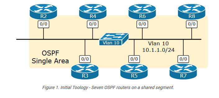
All routers run OSPF in a single area. The topology is fully converged, and there are no ongoing events.
The LSDB exchange on shared LANs
Let’s see what happens when we connect a new OSPF router to the same Vlan, as shown in the following diagram.
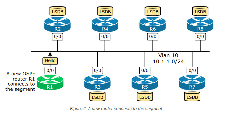
R1 starts sending OSPF Hello messages onto the LAN. Every router receives the Hello packet and inserts R1’s Router ID in their Hello messages. This results in R1 becoming an OSPF neighbor with all seven routers, as shown in the topology below. Is this a bad thing? Let’s continue ahead and see.
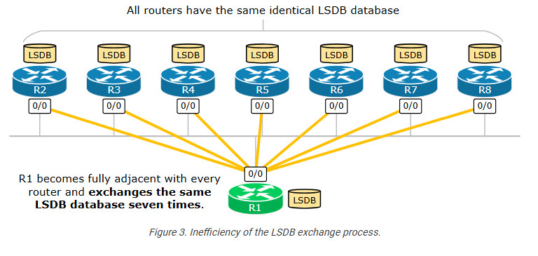
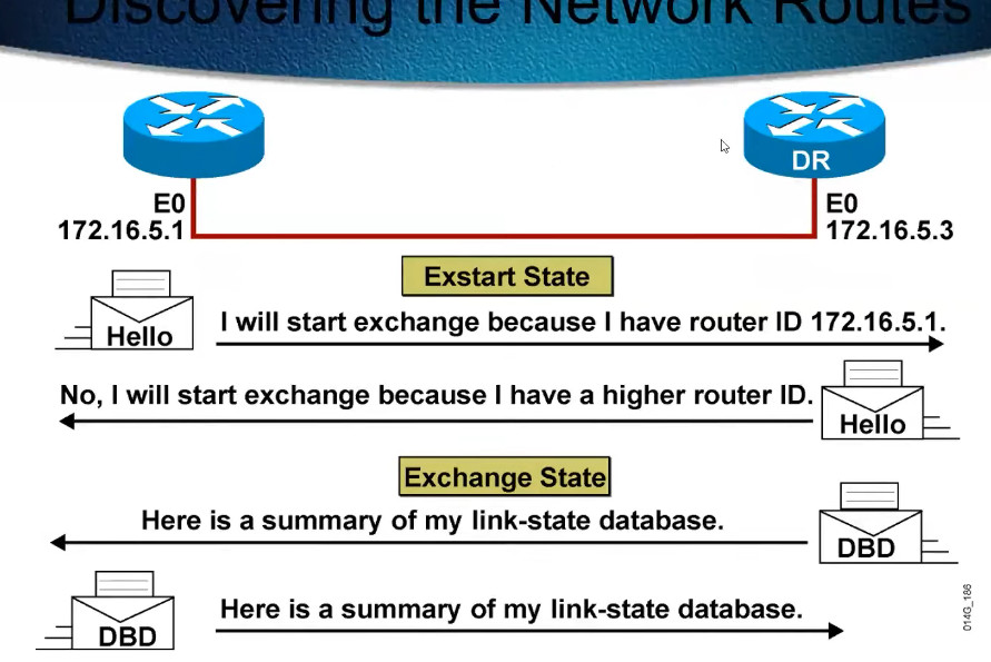
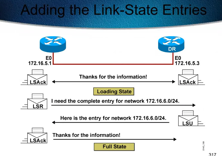
Since R1 is a brand-new router that has just been connected to the OSPF domain, its link-state database is basically empty. When R1 becomes a 2-way neighbor with each router, it then transitions to Exstart/Exchange/Loading phases and exchanges link-state information with every router. However, since all seven routers, R2 through R8, are in the same OSPF Area, they have identical link-state databases (LSDB). So, what actually happens is that R1 receives the same LSDB database seven times in a row. Does this seem efficient? Obviously not.
In the past, when routers had only a few MB of RAM and a single slow CPU, this inefficiency was a big deal. (the protocol is 30+ years old) That’s why network architects started to think of ways to optimize this process and make it work efficiently on multiaccess networks such as Ethernet LANs.
Let’s think about the inefficiency for a while:
Logically, it is enough for R1 to only receive the LSDB from one of the neighbors since all have identical LSDBs. But from which one? Well, this is the concept of the Designated Router – an automatically elected single router that handles the LSDB exchange on the shared LAN. Every other router exchanges link-state information only with the DR instead of separately with all neighbors.
The LSA flooding on shared LANsa
Additionally, every router becomes fully adjacent (neighbor in the state: Full) to every other device in the topology. This means there are n(n-1)/2 adjacencies on the segment, as shown in the diagram below. This is also inefficie
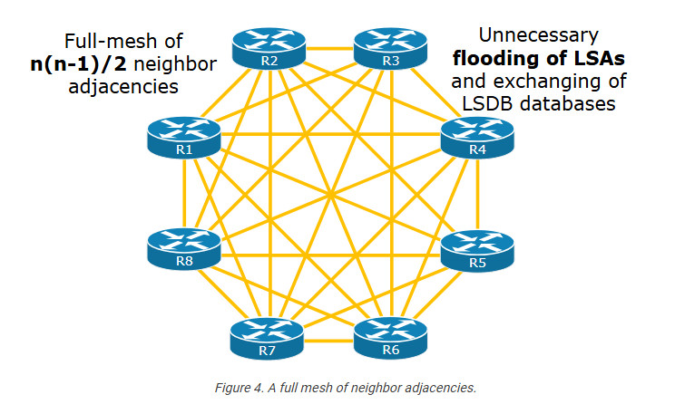
Upon a topology change in the area, such as an interface flap, every pair of routers exchanges LSA information, resulting in a massive flood of unnecessary identical LSA updates.
What is the Designated Router (DR)?
To overcome the inefficiencies we have just seen, OSPF introduced the concept of a Designated Router. When multiple routers sit on the same VLAN, they automatically elect one router to act as the Designated Router.
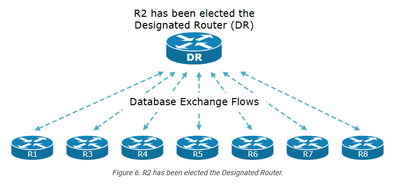
When a Designated Router is elected for the segment, routers only exchange database information with the DR, as shown in the diagram below. This significantly optimizes the LSDB exchange process.
Let’s compare this scenario with the one we showed earlier in Figure 4:
This is a massive optimization of the shared LAN segment. Especially back in the old days when routers had a few MB of RAM and a single slow CPU.
How does OSPF DR and BDR work?
Now, let’s zoom in a bit and see how the DR/BDR election process works.
The Election Process
The DR election process is based on a parameter in the OSPF Hello packet called Priority, which has values from 0 to 255 (28).
It is very important to remember the following aspects of the election process from the very beginning:
Let’s walk through a couple of scenarios to demonstrate how the election process works.
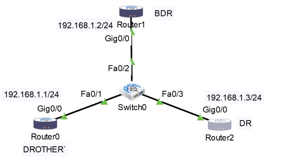
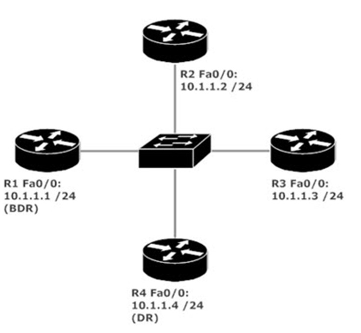
Scenario 1: DR election on a new link
We have a simple topology of four devices connected to the same VLAN via a layer two switch that has just been powered on. This clarification is very important because it means no DR has been elected yet, and the process starts from scratch.
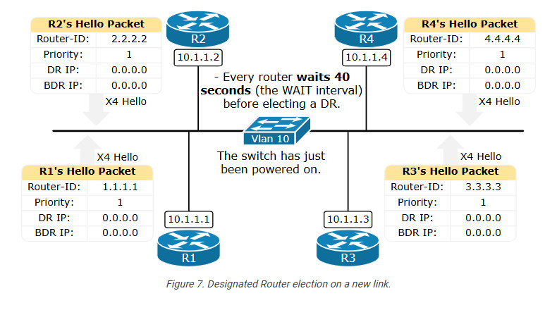
By default, every router sends a Hello packet every 10 seconds. In the Hello packet, every router includes its RID, the RIDs of other neighbors it hears, the default Priority of 1, and an empty DR and BDR IP address. Notice that the DR and BDR IP of 0.0.0.0 indicates that no Designated or Backup Designated routers have been elected yet.
During the WAIT interval of 40 seconds (equal to the DEAD timer or four Hello intervals), none of the routers can claim themselves as DR or BDR. Everybody is just listening. Additionally, none of the routers transition to Exstart/Exchange/Loading/Full neighbor states. Everyone is waiting for the DR/BDR election process to finish first.
The following diagram shows the OSPF neighboring states that routers go through before becoming fully adjacent and exchanging their LSDB. On multiaccess segments such as an Ethernet VLAN, routers become fully adjacent only with the DR and the BDR when such are elected.

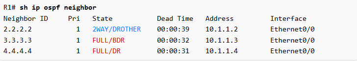
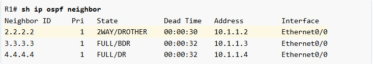
If we check the OSPF neighborship of R1 after the WAIT time has passed, we can see that it has established a full adjacency only with the DR (R4) and the BDR (R3), as shown in red. It stays in a 2-WAY state with every other router on the segment, for example with R2.
We can check what is the configured priority value and WAIT timer for a given VLAN by checking the OSPF parameters on the interface that connects to the VLAN. For example, let’s check the values of R1’s Eth0/0 interface using the show IP ospf interface command. It gives so much useful information.
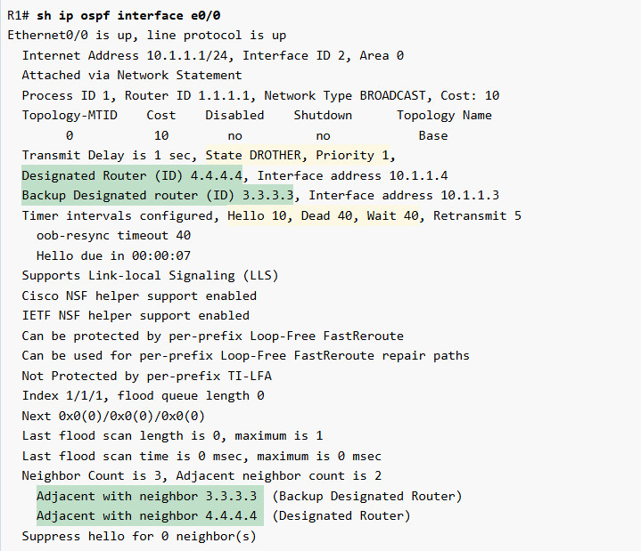
First, notice the state DROTHER. It means, “I am not the DR nor the BDR; I am simply another device.“. Next to it, you can see the configured priority. In this example, it is simply the default one.
Further down, highlighted in green, you can see who the currently elected DR and BDR are and what the WAIT timer for the interface is.
Notice that two routers that are both DROTHER do not become fully adjacent. They become neighbors in a 2-WAY state and stop there. They do not transition to the Exstart/Exchange/Loading phases (see Figure 8). For example, R1 and R2 are both DROTHER in the context of the Designated Router functionality (they are not the DR nor the BDR). That’s why they stay in 2-WAY neighboring states, as you can see in the output below.
Simple Way why Need DR BDR
In OSPF (Open Shortest Path First), the concepts of Designated Router (DR) and Backup Designated Router (BDR) are crucial for improving network efficiency and reducing the amount of routing information exchanged between routers, especially in broadcast and non-broadcast multi-access (NBMA) networks.
Here’s why DR and BDR are needed:
These roles are essential in OSPF networks to make routing more efficient and resilient, particularly in larger or more complex network topologies.
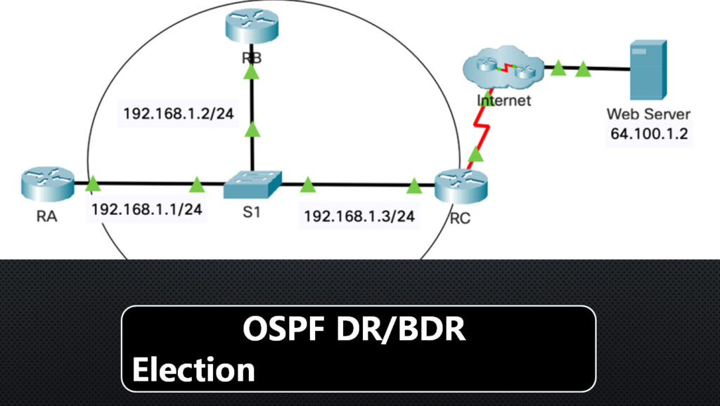
Router RA

en

conf t

interface GigabitEthernet0/0

ip ospf hello-interval 5

ip ospf dead-interval 20

ip ospf priority 150

ip ospf authentication message-digest

ip ospf message-digest-key 1 md5 Area0pa55

router ospf 1

network 192.168.1.0 0.0.0.255 area 0

area 0 authentication message-digest

End

Router RB

en

conf t

interface GigabitEthernet0/0

ip ospf hello-interval 5

ip ospf dead-interval 20

ip ospf priority 100

ip ospf authentication message-digest

ip ospf message-digest-key 1 md5 Area0pa55

router ospf 1

network 192.168.1.0 0.0.0.255 area 0

area 0 authentication message-digest

end
Router RC ASBR

en

conf t

interface GigabitEthernet0/0

ip ospf hello-interval 5

ip ospf dead-interval 20

ip ospf priority 50

ip ospf authentication message-digest

ip ospf message-digest-key 1 md5 Area0pa55

router ospf 1

passive-interface default

no passive-interface GigabitEthernet0/0

network 192.168.1.0 0.0.0.255 area 0

default-information originate

area 0 authentication message-digest

ip route 0.0.0.0 0.0.0.0 Serial0/0/0 end
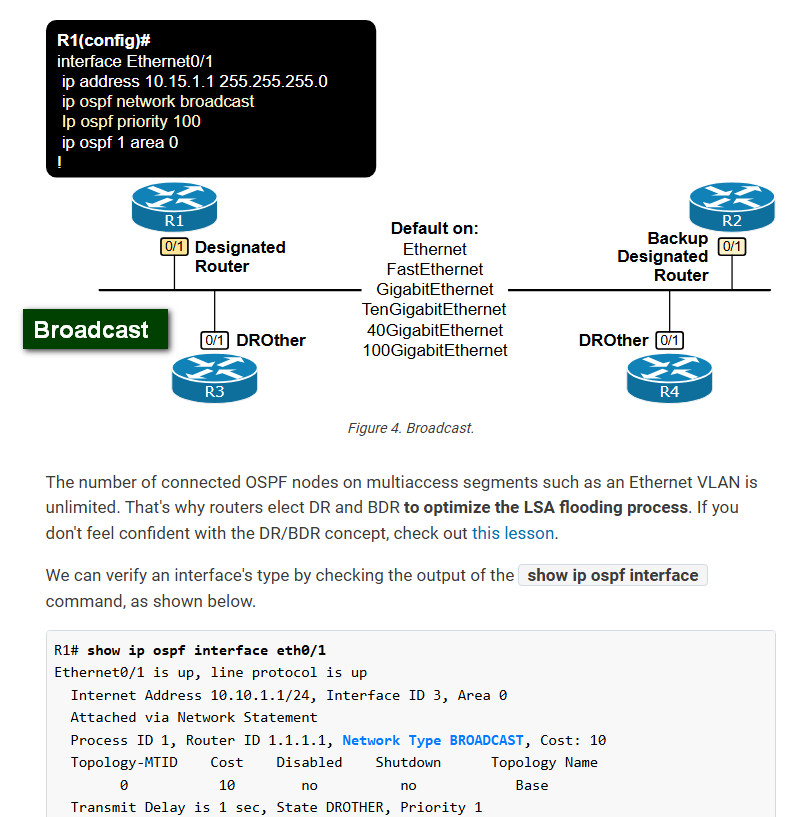
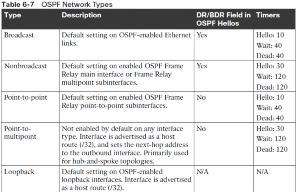
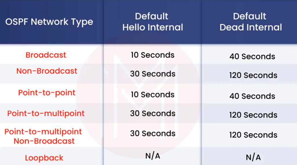
Broadcast
Non-Broadcast
Point-to-Point
Point-to-Multipoint Non-Broadcast
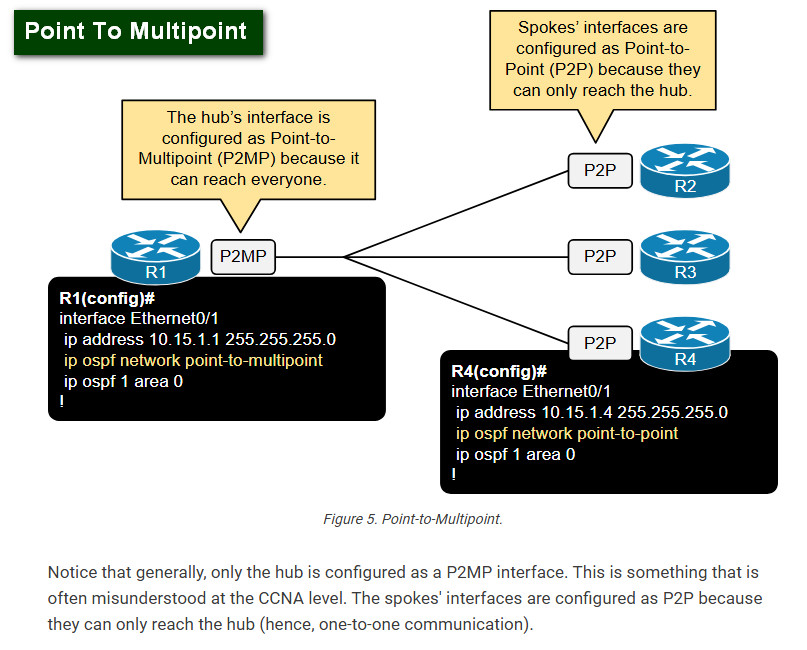
Point-to-Multipoint
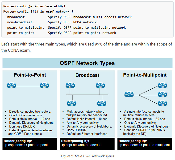
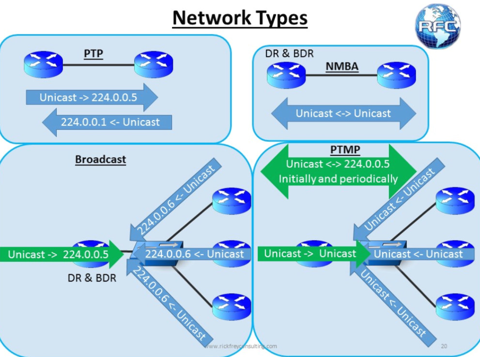
OSPF Network Types
OSPF defines five different network types to account for the different WAN technologies and their underlying properties. The network type is a configurable per-interface setting that tells the OSPF process how to establish and maintain neighborship over the given interface.


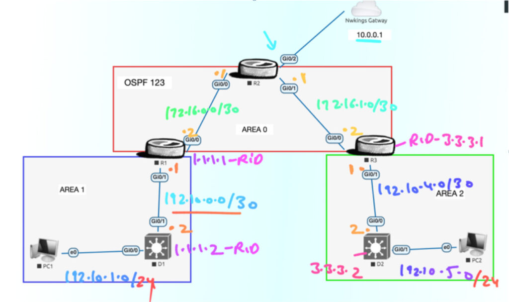
Router R1

hostname R1

no ip domain lookup

banner motd # This is R1, Implement Multi-Area OSPFv2 Lab#

interface gi0/0

ip add 172.16.0.2 255.255.255.252

no shut

Ip ospf 1 area 0

exit

interface GigabitEthernet0/1

ip address 192.10.0.1 255.255.255.252

no shut

Ip ospf 1 area 1

exit
Router R3

hostname R3

no ip domain lookup

banner motd # This is R3, Implement Multi-Area OSPFv2 Lab #

interface gi0/0

ip add 172.16.1.2 255.255.255.252

no shut

Ip ospf 1 area 0

exit

interface Gi0/1

ip address 192.10.4.1 255.255.255.252

no shut

Ip ospf 1 area 2

exit
hostname R2

no ip domain lookup

banner motd # This is R2, Implement Multi-Area OSPFv2 Lab #

interface gi0/0

ip add 172.16.0.1 255.255.255.252

no shut

exit

interface Gi0/1

ip address 172.16.1.1 255.255.255.252

no shut

exit

interface lo0

ip add 209.165.200.225 255.255.255.224

int gi0/2

ip address dhcp

no shutdown
NAT_Configuration

access-list 1 permit 192.10.1.0 0.0.0.255

access-list 1 permit 192.10.5.0 0.0.0.255

ip nat inside source list 1 interface gi0/2 overload

int gi0/2

ip nat outside

int gi0/0

ip nat inside

int gi0/1

ip nat inside
L3 Switch

hostname D1

conf t

no ip domain lookup

banner motd # This is D1, Implement Multi-Area OSPFv2 Lab #

interface gi0/1

no switchport

ip address 192.10.0.2 255.255.255.252

no shut

Ip ospf 1 area 1

Exit

interface gi0/0

no switchport

ip address 192.10.1.1 255.255.255.0

no shut

exit
L3 Switch

hostname D2

no ip domain looku

banner motd # This is D2, Implement Multi-Area OSPFv2 Lab #

interface gi0/0

no switchport

ip address 192.10.4.2 255.255.255.252

no shut

Ip ospf 1 area 2

exit

interface gi0/1

no switchport

ip address 192.10.5.1 255.255.255.0

no shut

exit

Understanding OSPF LSA types is necessary to master the OSPF routing protocol. In an OSPF routing domain, each node creates at least one type of LSA, which is the router LSA. A router may produce more LSAs depending on its functions (DR, BDR, ABR, or ASBR). The set of LSAs within an OSPF area constitutes the area’s link-state database, and it is consistent on all the area’s routers.
What is LSA in OSPF?
In an OSPF AS, a link statement advertisement (LSA) is a data format routers use to describe the links connected to them, OSPF adjacent neighbors, internal and external subnets, and ASBRs. Different OSPF LSA types are used by routers within an OSPF domain to build up the graph of the network for the sake of producing the SPF tree.
Each node in an OSPF autonomous system creates one or more LSAs based on its configuration and shares them with its adjacent neighbors. In addition, the router will also flood the latest version of any received LSA to its neighbors, except the sender and including the router that originated the LSA. This is if it is not the sender.
How Many OSPF LSA Types Do Exist?
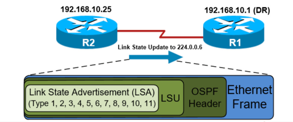
There are 11 LSA types in OSPF, and each LSA type is handled differently, with the combined set of all received and sent LSAs establishing the router’s link state database (LSDB). Cisco, Juniper, and Huawei are implementing the following ten OSPF LSA types on their routers, whereas RFC 2328’s specification for OSPFv2 defines only five LSA types:
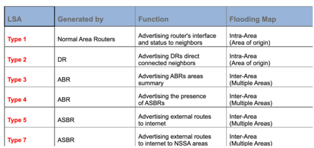
LSA Type 1 (Router LSA)
LSA Type 2 (Network LSA)
LSA Type 3 (Summary LSA)
LSA Type 4 (ASBR Summary LSA)
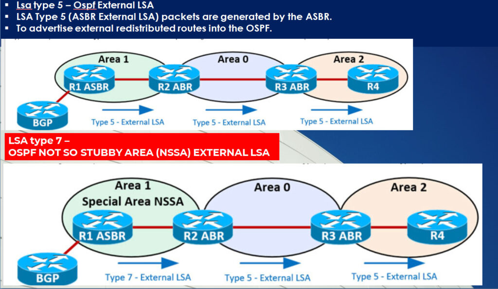
LSA Type 5 (Autonomous System LSA)
LSA Type 7 (NSSA external LSA)
LSA Type 8 (External-Attributes LSA)
LSA Type 9 (Link-local opaque LSA)
LSA Type 10 (Area-local opaque LSA)
LSA Type 11 (Autonomous System opaque LSA))
LSA – Link state advertisments.
The OSPF LSA contains a complete list of networks advertised from that router. OSPF uses six LSA types for IPv4 routing:
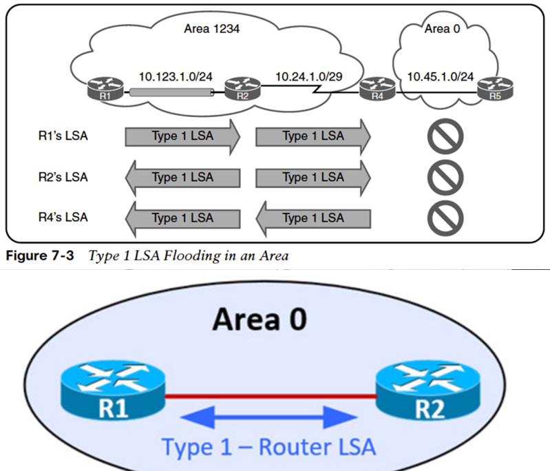
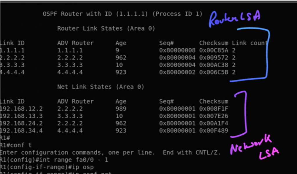
LSA Type 1 – Router LSA
LSA Type 1 (Router LSA) packets are sent between routers within the same area.
LSA Type 1 Packets exchanged between OSPF routers within the same area.
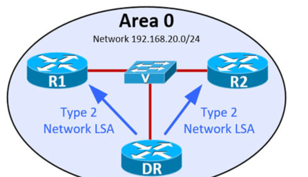
LSA TYPE 2 – NETWORK LSA
LSA Type 2 (Network LSA) packets are generated by the Designated Router (DR) to describe all routers connected to its segment directly.
LSA Type 2 packets are flooded between neighbors in the same area of origin and remain within that area.
LSA Type 2 Packets exchanged between OSPF DR and neighbor routers


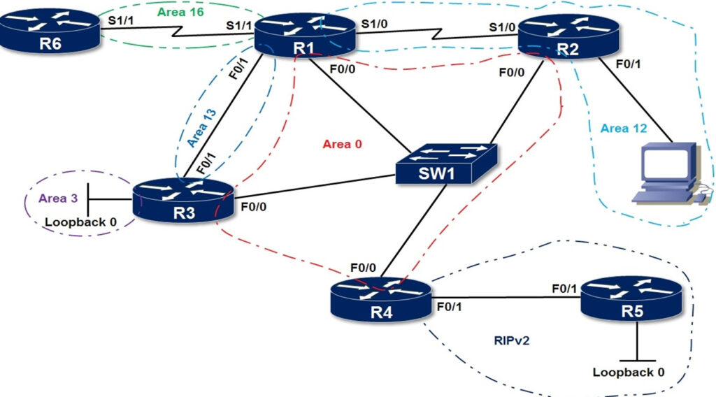
hostname R1
router ospf 1
router-id 1.1.1.1
interface FastEthernet0/0
ip address 10.0.0.1 255.255.255.0
ip ospf 1 area 0
no shut
interface FastEthernet0/1
ip address 10.0.13.1 255.255.255.0
ip ospf 1 area 13
no shutdown
interface Serial1/0
ip address 10.0.12.1 255.255.255.0
ip ospf 1 area 12
no shut
interface Serial1/1
ip address 10.0.16.1 255.255.255.0
ip ospf 1 area 16
no shutdown
hostname R2
router ospf 1
router-id 2.2.2.2
interface FastEthernet0/0
ip address 10.0.0.2 255.255.255.0
ip ospf 1 area 0
no shut
interface FastEthernet0/1
ip address 10.0.2.2 255.255.255.0
ip ospf 1 area 12
no shut
interface Serial1/0
ip address 10.0.12.2 255.255.255.0
ip ospf 1 area 12
no shut
hostname R3
router ospf 1
router-id 3.3.3.3
interface FastEthernet0/0
ip address 10.0.0.3 255.255.255.0
ip ospf 1 area 0
no shut
interface FastEthernet0/1
ip address 10.0.13.3 255.255.255.0
ip ospf 1 area 13
no shut
interface loopback0
ip address 10.0.3.3 255.255.255.0
ip ospf 1 area 3
hostname R4
router rip
version 2
network 10.0.0.0
no auto-summary
redistribute ospf 1 metric 1
router ospf 1
router-id 4.4.4.4
redistribute rip subnets
interface FastEthernet0/0
ip address 10.0.0.4 255.255.255.0
ip ospf 1 area 0
no shut
interface FastEthernet0/1
ip address 10.0.45.4 255.255.255.0
no shutdown
hostname R5
interface FastEthernet0/1
ip address 10.0.45.5 255.255.255.0
no shut
interface loopback0
ip address 10.0.5.5 255.255.255.0
router rip
version 2
network 10.0.0.0
no auto-summary
hostname R6
router ospf 1
router-id 6.6.6.6
interface serial 1/1
ip address 10.0.16.6 255.255.255.0
ip ospf 1 area 16
no shutdown