- 8777701917
- info@saikatinfotech.com
- Basirhat W.B

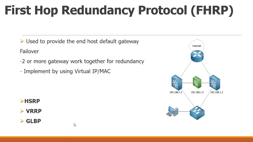
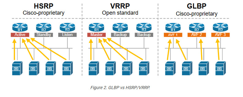
Redundancy” protocols supported by Cisco devices. These are Hot Standby Router Protocol (HSRP), Virtual Router Redundancy Protocol (VRRP) and Gateway Load Balancing Protocol (GLBP).
The main purpose of the above protocols is to provide redundancy to the default gateway (router or Layer3 switch) in a LAN environment.
Usually in a LAN we configure a default gateway IP on all users’ computers in order to reach the Internet (or other networks).
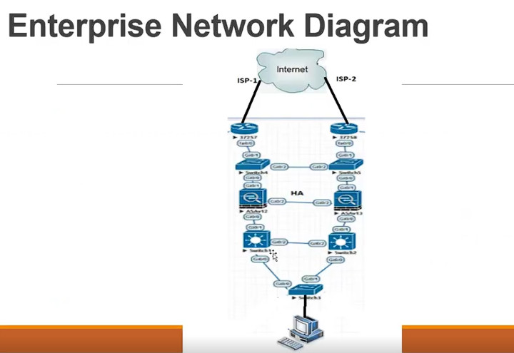
Although the above is the most commonly used scenario, we can also use HSRP/VRRP/GLBP in conjunction with some other mechanisms and protocols (such as BGP for example) to implement ISP redundancy (Dual WAN connectivity).
However in this particular article we’ll just discuss a simple implementation of providing redundancy to two routers in a LAN and provide comparison of VRRP Vs HSRP Vs GLBP which are supported by Cisco.
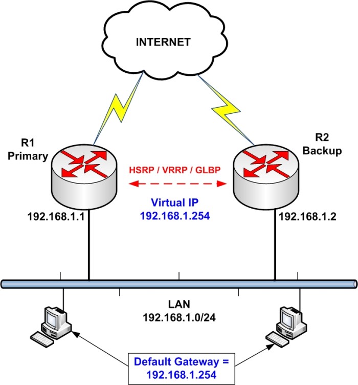
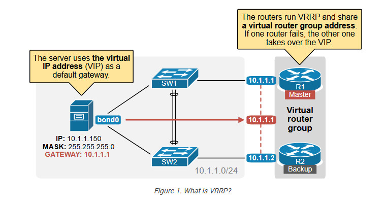
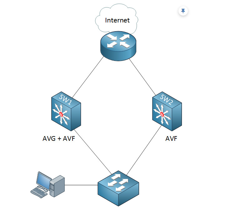
In our simple network above, we want to provide redundancy to the border routers (R1 and R2) which connect users to the Internet. By configuring one of the redundancy protocols (HSRP, VRRP, GLBP) we can achieve just that.
Each router has its own IP configured to its LAN interface (192.168.1.1 on R1 and 192.168.1.2 on R2). However, a Virtual IP (192.168.1.254) will also exist which will serve as the default gateway for the whole LAN. No matter which router is active or if we have one failed router, the Virtual IP will still exist in order to route packets from the users.
Basic Configuration of HSRP – VRRP – GLBP
Before moving into our comparison between the 3 protocols, let’s first see the basic configuration for each one:
HSRP Configuration
R1
interface Ethernet0/1
description LAN Interface of Active Router
ip address 192.168.1.1 255.255.255.0
standby 1 ip 192.168.1.254 <—- Create HSRP Group 1 and assign Virtual IP
standby 1 priority 101 <—- Assign priority above 100 to make this the primary router
standby 1 preempt <—- Makes router active if it has higher priority
R2
interface Ethernet0/1
description LAN Interface of Standby Router
ip address 192.168.1.2 255.255.255.0
standby 1 ip 192.168.1.254 <—- Create HSRP Group 1 and assign Virtual IP
standby 1 preempt <—- Makes router active if it has higher priority
VRRP Configuration
R1
interface Ethernet0/1
description LAN Interface of Active Router
ip address 192.168.1.1 255.255.255.0
vrrp 1 ip 192.168.1.254 <—- Create VRRP Group 1 and assign Virtual IP
vrrp 1 priority 101 <—- Assign priority above 100 to make this the primary router
vrrp 1 preempt <—- Makes router active if it has higher priority
R2
interface Ethernet0/1
description LAN Interface of Standby Router
ip address 192.168.1.2 255.255.255.0
vrrp 1 ip 192.168.1.254 <—- Create VRRP Group 1 and assign Virtual IP
vrrp 1 preempt <—- Makes router active if it has higher priority
GLBP Configuration
R1
interface Ethernet0/1
description LAN Interface of Primary Router
ip address 192.168.1.1 255.255.255.0
glbp 1 ip 192.168.1.254 <—- Create GLBP Group 1 and assign Virtual IP
glbp 1 priority 101 <—- Assign priority above 100 to make this the primary router
glbp 1 preempt <—- Makes router active if it has higher priority
glbp 1 load-balancing round-robin <—- Configure round-robin balancing of traffic
R2
interface Ethernet0/1
description LAN Interface of Secondary Router
ip address 192.168.1.2 255.255.255.0
glbp 1 ip 192.168.1.254 <—- Create GLBP Group 1 and assign Virtual IP
glbp 1 preempt <—- Makes router active if it has higher priority
glbp 1 load-balancing round-robin <—- Configure round-robin balancing of traffic
Comparison between HSRP Vs VRRP Vs GLBP
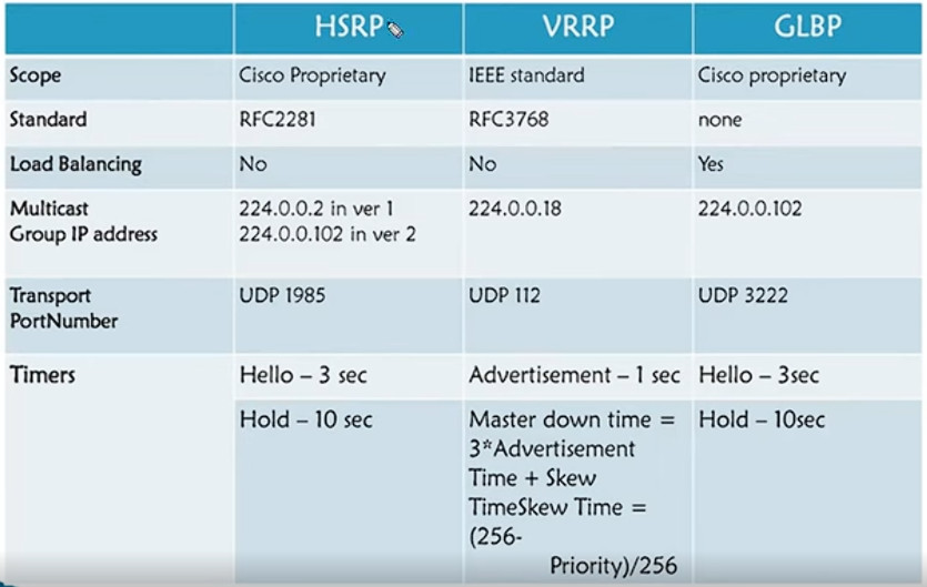
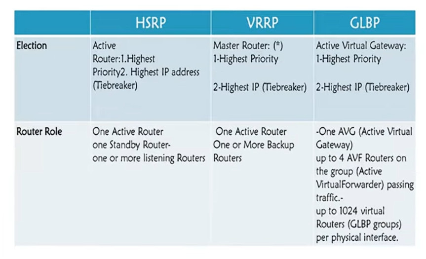
Now let’s move to the main purpose of this article: To see similarities and differences between the 3 protocols. I’ll just state briefly some comparison points below and then use a table to compare more features.
Now let’s put some more comparison info in a table:
| HSRP | VRRP | GLBP |
| Cisco Proprietary | Standardized | Cisco Proprietary |
| Active and Standby mode only | Active and Standby mode only | Multiple routers pass traffic thus achieving load balancing |
| Must configure a separate IP for the Virtual. | Virtual IP can be same as physical IP of one of the routers | Must configure a separate IP for the Virtual. |
| Default priority = 100 | Default priority = 100 | Default priority = 100 |
| Higher priority (above 100) makes router active. Otherwise, higher IP makes router active. | Higher priority (above 100) makes router active. Otherwise, higher IP makes router active. | Higher priority (above 100) makes router primary forwarder. Otherwise, higher IP makes router primary forwarder. |
| Tracking supported (e.g interface state, routing info, reachability of remote host etc) | Tracking supported (e.g interface state, routing info, reachability of remote host etc) | Tracking supported (e.g interface state, routing info, reachability of remote host etc) |
| Supports IPv6 | No support for IPv6 on the original VRRP implementation. However, VRRPv3 (RFC 5798) now supports it. | Supports IPv6 |
| Supports timer and delay adjustments for failover | Supports timer and delay adjustments for failover | Supports timer and delay adjustments for failover |
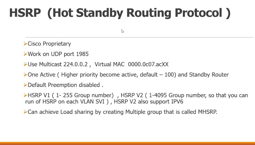
What is HSRP?
Hot Standby Router Protocol (HSRP) is a Cisco proprietary FHRP protocol that enables two or more routers to work together, acting as a highly available default gateway to local hosts. HSRP operates in an active/standby model and implements the concept of a Virtual IP address (VIP), as shown in the diagram below.
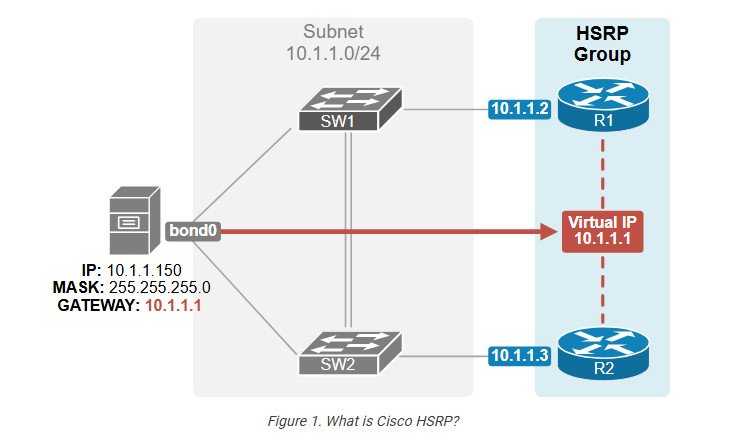
Notice that R1’s physical interface has an IP address of 10.1.1.2, and R2’s physical interface has 10.1.1.3. However, both routers run HSRP and share the virtual IP address 10.1.1.1. The VIP is a normal IP address in the same local subnet but is not configured on any physical router interface (hence “virtual”).

How does HSRP work?
This was the protocol’s high-level overview. Now, let’s examine the protocol’s most important aspects and operation in more detail.
Virtual IP (VIP) and Virtual MAC address (VMAC)
HSRP creates a virtual IP address (VIP) and a virtual MAC address (VMAC) that hosts in the network use as their gateway. The active router acts as if the virtual IP address is configured on its physical interface that connects to the local subnet, as shown in the diagram below.
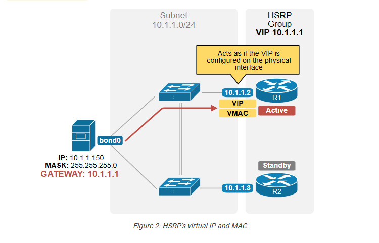
For example, a host is configured with the default gateway 10.1.1.1 (the VIP). When the host sends an ARP Request for the default gateway 10.1.1.1, the active router (R1) replies to ARP requests for the VIP with the virtual MAC address (VMAC).
The other router remains in standby mode and is ready to take over. When the active router fails, the standby router becomes active. What does that mean, though? This means it starts acting as if the virtual IP address is configured on its physical interface, as shown in the diagram below.
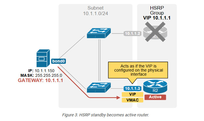
When a host sends an ARP Request for 10.1.1.1 (the VIP) and R1 is unavailable, the standby router becomes active and replies with the virtual MAC address (the VMAC).
HSRP Control Plane
Now, let’s examine the protocol’s control plane that manages the exchange of messages and states between routers participating in an HSRP group.
Hello messages
HSRP is configured per router interface. When we configure an interface as part of an HSRP group, it starts sending periodic HSRP Hello messages to multicast address 224.0.0.2 (all routers link-local multicast). These packets use UDP port 1985
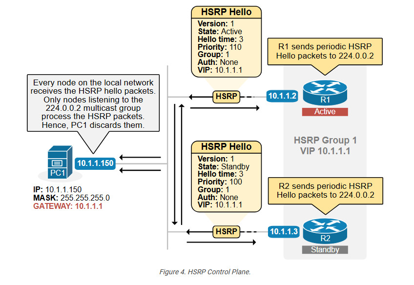
As the diagram above shows, Hello messages contain essential information. The most important parameter is the HSRP group number. Two or more routers that want to establish an HSRP relationship and share a common virtual IP address must use the same Group number.
For example, in the diagram above, both routers use group number 1.
The other very important parameters in the Hello messages are the priority value and the virtual IP address.
Priority
The router’s priority determines the active router in the group. One HSRP group can only have one active router. Each router in the group is assigned a priority value between 0 and 255, as shown in the output below. If no priority is explicitly set, the device assigns the default priority value 100.
R1(config)# interface GigabitEthernet0/1
R1(config-if)# standby 1 ip 10.1.1.1
R1(config-if)# standby 1 priority 110
In the end, the device with the highest priority becomes the active router. Pay attention to the following arguments in the configuration commands shown above:
Active router election
Based on the priority values of every router, the HSRP election process determines which router will become active and which will be the standby router in an HSRP group. The process works in two steps:
Once an active router has been elected, the router with the second-highest priority (or IP address in case of a tie) is elected as the standby router. It will take over if the active router fails.
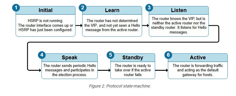
A router interface that runs HSRP does not immediately become an Active or Standby router. It first goes through the protocol’s state machine to determine how many routers participate in the HSRP group and what its state should be. The following diagram explains the purpose of each state.
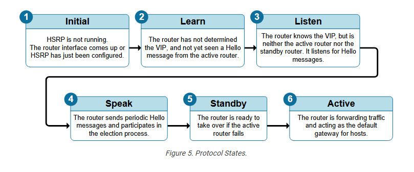
In the HSRP configuration lab, we will discuss the states in more detail. Using debug messages, we will observe how a device moves through the states before it becomes active or standby. Keep in mind that the HSRP states are a common drag-and-drop question on the CCNA exam. Although they are pretty easy to figure out using simple logic, it is good to spend time understanding each state.
Versions
Cisco devices support two HSRP versions: version 1 and version 2. These versions differ in several aspects, such as multicast IP addresses and message formats. Because of these differences, all routers within the same group must run the same version. If two routers in the same group are mistakenly configured with different versions, they will be unable to communicate and will ignore each other.
| Capability | Version 1 | Version 2 |
| Hello timer units | Seconds | Milliseconds |
| Supports both IPv4 and IPv6 | No (only IPv4) | Yes |
| Number of groups supported | 256 (from 0 to 255) | 4096 (from 0 to 4095) |
| Virtual MAC (– or — is the HSRP group number in HEX) | 0000.0C07.AC– | 0000.0C9F.F— |
| Multicast address | 224.0.0.2 | 224.0.0.102 |
Version 2 offers several advantages over version 1. It introduced support for IPv6 and enables faster convergence during changes by using shorter Hello timers. In contrast, HSRPv1 typically had a minimum Hello timer of 1 second. The table above outlines the key differences between the two protocol versions. Even though version 2 is superior to v1, HSRPv1 is far more common in real–world deployments than HSRPv2.
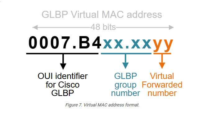
The virtual MAC address
The HSRPv1 virtual MAC address is a Layer 2 address associated with the virtual IP address (VIP) configured for the HSRP group. It has the following format:a
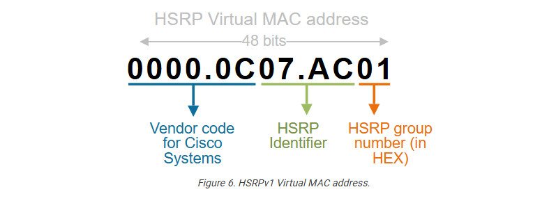
For example, if the HSRPv1 group number is 1, the virtual MAC address will be as follows:
0000.0C07.AC01
Let’s break it down into pieces:
If you want to become a good network engineer, you must remember this MAC address structure. It is a very common part of Cisco exam questions. Additionally, it is very common in real-world troubleshooting situations to check ARP tables and figure out that a particular IP address is a virtual one (based on the bound MAC address). Let’s see a few more examples:
The MAC address for Group 5
0000.0C07.AC05

The MAC address for Group 10
000.0C07.AC0A

The MAC address for Group 150
0000.0C07.AC96

The MAC address for Group 255
0000.0C07.ACFF
Notice that the Group number is converted to a hexadecimal number in the MAC address (in red). Also, notice that the largest possible HEX number with two HEX digits is FF, which is 255 in decimal. That’s why Cisco routers support a maximum of 256 HSRP groups per interface (depending on the platform and software version).
The HSRPv2 uses a different MAC address 0000.0C9F.Fxxx, where xxx is the group number in HEX. However, the logic is exactly the same. Obviously, it supports more group numbers – 4096.
HSRP Data Plane
Once the protocol state machine has gone through the states, the protocol is converged and ready to forward traffic. Let’s quickly examine how traffic forwarding happens in the data plane. How does host traffic end up on the Active router? The following diagram explains how the data plane works.
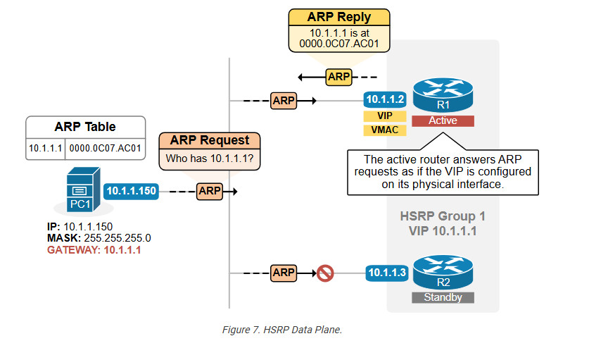
Once an active router is elected, it starts acting as if the virtual IP address is configured on its physical interface that connects to the subnet. In our instance, R1 is the active router for group 1 with VIP 10.1.1.1. Even though its physical interface has IP address 10.1.1.2, it starts replying to ARP requests for the VIP address 10.1.1.1 with the VMAC address, as shown in the diagram above. Therefore, the hosts’ ARP tables have an entry that binds the VIP (10.1.1.1) with the VMAC (0000.0c07.ac01), as shown in the output below.
Microsoft Windows [Version 10.0.22631.4317]
(c) Microsoft Corporation. All rights reserved.
C:\Users\ivan> arp -a
Interface: 10.1.1.150 --- 0x7
Internet Address Physical Address Type
10.1.1.1 00-00-0c-07-ac-01 dynamic
10.1.1.32 70-da-01-aa-3c-3f dynamic
239.255.255.250 01-00-5e-7f-ff-fa static
255.255.255.255 ff-ff-ff-ff-ff-ff static
In the end, the Ethernet switches forward all frames destined to the VMAC to R1 (the active router).
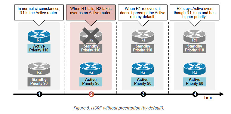
Preemption
Preemption is a feature in the Hot Standby Router Protocol (HSRP) that allows a higher-priority device to become the active router when it becomes available.
Typically, the device with the highest priority becomes the active router. If it fails, the device with the next highest priority takes over. Without preemption, the original active router will not regain its role when it returns online, even if it has a higher priority. Instead, the current active router will continue in that role until it fails, as shown in the diagram below.
With preemption enabled, the higher-priority router can automatically take back the active role once it recovers and rejoins the network, as shown in the diagram below. This feature ensures that the router with the best resources or configuration is always the active one, maintaining optimal performance.
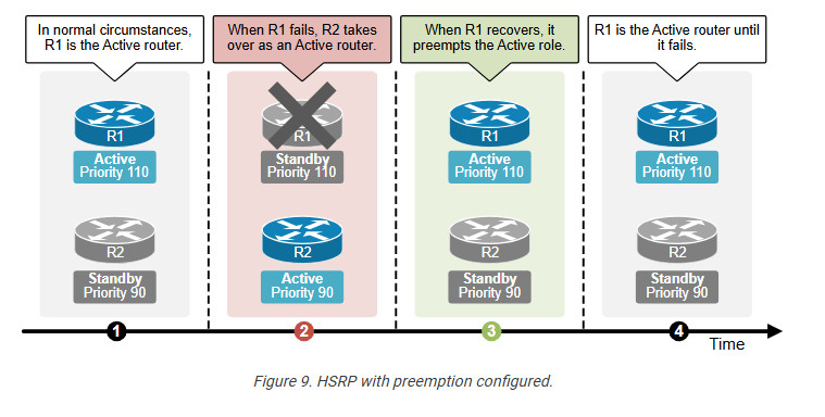
For preemption to work, it must be explicitly configured on the router, and the priority value should also be set to reflect its importance in the group.
Router(config-if)# standby 1 preempt
It is very important to remember that preemption is disabled by default. If you want the router with the highest priority to preempt the Active role when available, you must configure the capability explicitly, as shown in the output above.
IMPORTANT: Preemption is disabled by default in HSRP.
Now that we have reviewed how the protocol works let’s look at the most common use cases in real-world scenarios.
HSRP Use cases
There are a few very common scenarios when we use the Hot Standby Routing Protocol in production networks.
Resilient Default Gateway
Of course, the protocol’s most common use case is providing a resilient default gateway to hosts by allowing two or more routers to share a virtual IP address. One router is active, and the others are on standby. A standby router takes over if the active router fails, ensuring uninterrupted gateway availability.
This capability is used in 99.9% of all modern networks because default gateway redundancy is essential for the overall availability of host connectivity.
Load balancing
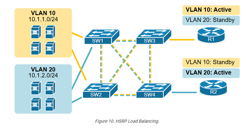
We have said that the protocol is configured per interface, which is effectively per subnet. When a device has many interfaces connected to many subnets, it typically participates in many HSRP groups. Suppose we have two routers (R1 and R2) that connect to multiple host subnets. In such a scenario, If we configure R1 to be the active router for every subnet, we end up in the following situation:
A better design is distributing traffic across the two routers by making one device active for some subnets and the other active for others, as shown in the diagram below.
We can go even further and configure two HSRP groups in the same subnet with different VIP addresses. Then, we can configure some of the hosts to use one of the VIPs as the default gateway and the other half to use the second VIP. The diagram below illustrates this idea.
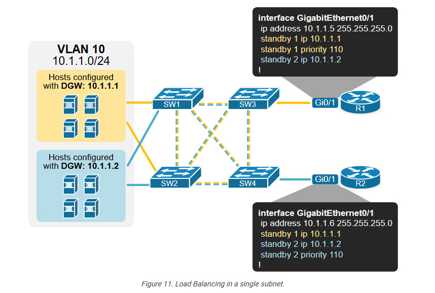
Notice that we configure multiple HSRP groups on a single interface. Each group has its own virtual IP address, which different hosts can use as their default gateway.
Although this design is not very common, it can be useful in scenarios where large subnets have many hosts transmitting high data volumes. If we don’t balance the traffic to both routers, one can easily be overutilized while the other is underutilized.
VIP as IP next hop
Another common use case is using HSRP VIP as the next-hop IP address in static routing. A static route can point to a virtual IP instead of a physical router IP, ensuring continuity in routing even if a next-hop device fails.
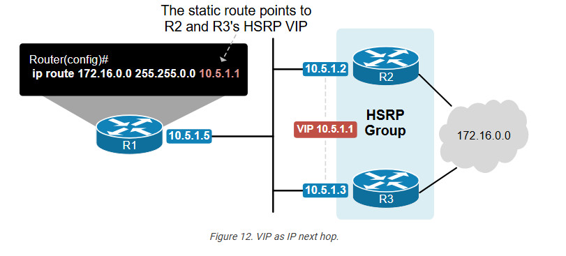
For example, we can configure a static route on R1 to point to either of the next-hop devices (R2 and R3). However, if that device fails, we will lose the static route. A better design is configuring the static route to point to a virtual IP address, as shown in the diagram above. In that case, even if one of the next-hop devices fails, the other takes over, and the static route still provides connectivity to the destination network.
Interface Tracking
Another capability available in all FHRPs monitors the status of other IOS functions. Cisco devices support tracking the state of interfaces, routes in the IP routing table, and various other objects. If a tracked interface fails, the protocol lowers the configured priority value.
The example below shows the most common use case of this capability. We have a dual-homed network with two WAN routers. The routers run HSRP to provide a resilient default gateway to hosts.
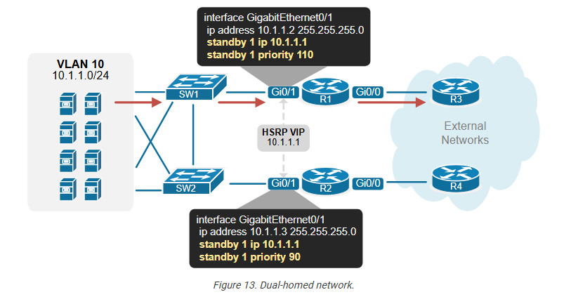
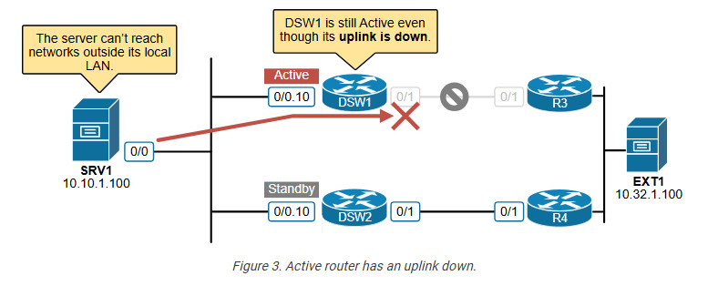
Notice that R1 is the active router, while R2 is the standby one. Therefore, all host traffic goes to R1 in normal circumstances. So far, so good; there is no problem here. However, let’s see what happens if one of the WAN links goes down. For example, R1’s uplink goes down, as shown in the diagram below.
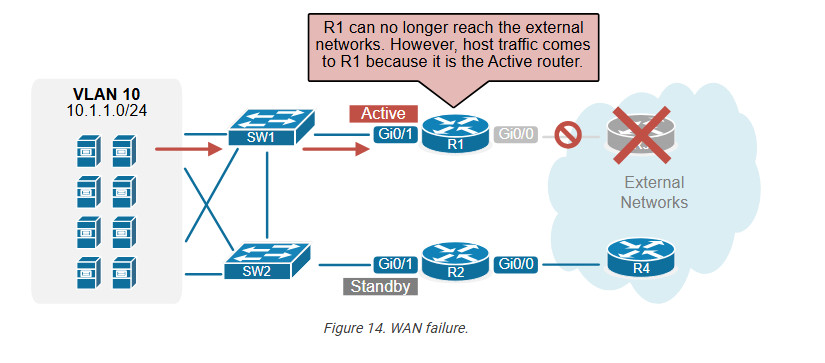
At this point, traffic from hosts still goes to R1 (because it is still the active device). However, R1 is not connected to the external world because its uplink is down. Depending on the routing design, this could lead to a complete outage for the hosts. Even if there is no outage, the traffic path becomes inefficient. This is where the interface tracking feature comes into play.
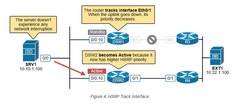
HSRP interface tracking monitors the status of a specific interface and dynamically adjusts the HSRP priority based on the operational state of the tracked interface. For example, R1 is the active device, and its tracked interface fails. The protocol immediately decreases the HSRP priority of the router with the configured value (50). At this point, the standby router’s priority becomes higher than R1’s current priority of 60 (110-50). Hence, R2 preempts the active role for the time being until R1’s uplink goes up again.
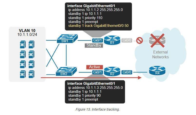
Now, the traffic from hosts goes directly to R2 and the external networks, which is the most efficient network path in this situation.
Lab #4.1 – Configuring HSRP
In this lesson, we will demonstrate how to configure HSRP on Cisco routers. At the end of the lesson, you can download the EVE-NG file and practice the lab in your home virtualized environment.
Lab Initial State
The diagram below shows the customer network we will work with. There are two local Vlans: Vlan10 with subnet 10.10.1.0/24 and Vlan 20 with subnet 10.20.1.0/24.
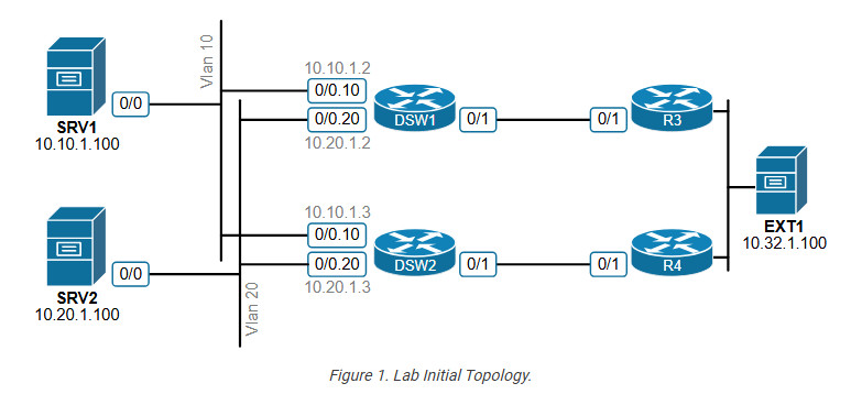
The hosts in vlan 10 are configured with a default gateway of 10.10.1.1, while those in vlan 20 are configured with 10.20.1.1. There is no first-hop redundancy protocol configured on the local routers.
Lab Requirements
An engineer configured the customer network but didn’t manage to finish. The customer has contacted you to finish the configuration based on the requirements below. There is no information on the current state of the configuration.
Try to complete the objectives yourself and then return to cross-check your solution with ours.
Lab Configuration
Let’s start with the first two requirements and then verify if everything works as expected. Then, we can move to requirement 3 and make all verifications.
Requirement 1
We need to configure an HSRP group 10 in vlan 10 with VIP address 10.10.1.1. The HSRP timers must be 1-second Hello and 3-second Hold timers. DSW1 must be the active router, and preemption must be enabled.
DSW1# configure terminal
interface Ethernet0/0.10
ip address 10.10.1.2 255.255.255.0
standby 10 ip 10.10.1.1
standby 10 priority 110
standby 10 timers 1 3
standby 10 preempt
!
The output above shows how we configure DSW1. Notice that we set priority 110 so that it can become the active router. Now, let’s configure DSW2 as a standby router.
DSW2# configure terminal
interface Ethernet0/0.10
ip address 10.10.1.3 255.255.255.0
standby 10 ip 10.10.1.1
standby 10 timers 1 3
standby 10 preempt
!
Notice that we don’t set any priority. Therefore, DSW2 will have the default priority of 100.
Requirement 2
Now, let’s configure the resilient default gateway in the other vlan – vlan 20. We must use HSRP version 2 with VIP 10.20.1.1 and timers 1 and 3. DSW2 must be the active router.
DSW1# configure terminal
interface Ethernet0/0.20
ip address 10.20.1.2 255.255.255.0
standby version 2
standby 20 ip 10.20.1.1
standby 20 timers 2 6
standby 20 preempt
!
Notice that we don’t configure any priority value for DSW1, so it has the default value of 100.
DSW2# configure terminal
interface Ethernet0/0.20
ip address 10.20.1.3 255.255.255.0
standby version 2
standby 20 ip 10.20.1.1
standby 20 timers 2 6
standby 20 priority 110
standby 20 preempt
!
Notice that we set priority 110 on DSW2 so it becomes the active router.
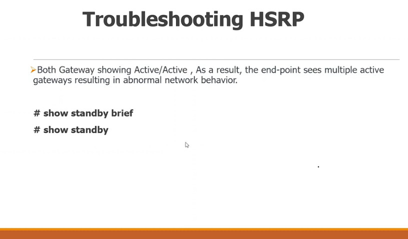
Now, we can check the HSRP state on DSW1 using the show standby brief command, as shown in the output below. Notice that the router reports it is the active router in Vlan 10 and the standby router in vlan 20.
DSW1# show standby brief
P indicates configured to preempt.
|
Interface Grp Pri P State Active Standby Virtual IP
Et0/0.10 10 110 P Active local 10.10.1.3 10.10.1.1
Et0/0.20 20 100 P Standby 10.20.1.3 local 10.20.1.1
If we want to have more details about the HSRP states, we use the show standby command, as shown below.

DSW1# show standby
Ethernet0/0.10 - Group 10
State is Active
2 state changes, last state change 00:06:48
Virtual IP address is 10.10.1.1
Active virtual MAC address is 0000.0c07.ac0a (MAC In Use)
Local virtual MAC address is 0000.0c07.ac0a (v1 default)
Hello time 1 sec, hold time 3 sec
Next hello sent in 0.576 secs
Preemption enabled
Active router is local
Standby router is 10.10.1.3, priority 100 (expires in 3.264 sec)
Priority 110 (configured 110)
Group name is "hsrp-Et0/0.10-10" (default)
FLAGS: 1/1

Ethernet0/0.20 - Group 20 (version 2)
State is Standby
4 state changes, last state change 00:00:41
Virtual IP address is 10.20.1.1
Active virtual MAC address is 0000.0c9f.f014 (MAC Not In Use)
Local virtual MAC address is 0000.0c9f.f014 (v2 default)
Hello time 2 sec, hold time 6 sec
Next hello sent in 0.864 secs
Preemption enabled
Active router is 10.20.1.3, priority 110 (expires in 6.240 sec)
MAC address is aabb.cc00.9000
Standby router is local
Priority 100 (default 100)
Group name is "hsrp-Et0/0.20-20" (default)
FLAGS: 0/1
We can verify the same for the other router DSW2. It is the standby router for Vlan 10 and active for Vlan 20. Notice that the virtual MAC address is different for the different HSRP groups because group 10 is configured with HSRPv1, and group 20 is configured with HSRPv2.
DSW2# show standby
Ethernet0/0.10 - Group 10
State is Standby
1 state change, last state change 00:06:54
Virtual IP address is 10.10.1.1
Active virtual MAC address is 0000.0c07.ac0a (MAC Not In Use)
Local virtual MAC address is 0000.0c07.ac0a (v1 default)
Hello time 1 sec, hold time 3 sec
Next hello sent in 0.640 secs
Preemption enabled
Active router is 10.10.1.2, priority 110 (expires in 2.912 sec)
Standby router is local
Priority 100 (default 100)
Group name is "hsrp-Et0/0.10-10" (default)
FLAGS: 0/1

Ethernet0/0.20 - Group 20 (version 2)
State is Active
2 state changes, last state change 00:02:44
Virtual IP address is 10.20.1.1
Active virtual MAC address is 0000.0c9f.f014 (MAC In Use)
Local virtual MAC address is 0000.0c9f.f014 (v2 default)
Hello time 2 sec, hold time 6 sec
Next hello sent in 1.408 secs
Preemption enabled
Active router is local
Standby router is 10.20.1.2, priority 100 (expires in 6.544 sec)
Priority 110 (configured 110)
Group name is "hsrp-Et0/0.20-20" (default)
FLAGS: 1/1
HSRP States
If we enable debugging on one of the routers, we can see the state changes that the protocol goes through (highlighted in green)
*Jan3 10:49: HSRP: Vl10 Interface UP
*Jan3 10:49: HSRP: Vl10 Initialize swsb, Intf state Up
*Jan3 10:49: HSRP: Vl10 Starting minimum intf delay (1 secs) - uptime 1623
*Jan3 10:49: HSRP: Vl10 Grp 1 Set virtual MAC 0000.0c07.ac01 type: v1 default
*Jan3 10:49: HSRP: Vl10 Added 10.10.1.1 to hash table
*Jan3 10:49: HSRP: Vl10 Grp 1 fhrp mac, reserved 0000.0c07.ac01, type: v1 default
*Jan3 10:49: HSRP: Vl10 Grp 1 Disabled -> Init
*Jan3 10:49: HSRP: Vl10 IP Redundancy "hsrp-Vl10-1" update, Disabled -> Init
*Jan3 10:49: HSRP: Vl10 Grp 1 Priority 100 -> 110
*Jan3 10:49: HSRP: Vl10 Intf min delay expired - uptime 1624
*Jan3 10:49: HSRP: Vl10 Grp 1 Init: a/HSRP enabled
*Jan3 10:49: HSRP: Vl10 Grp 1 Init -> Listen
*Jan3 10:49: HSRP: Vl10 Grp 1 Redundancy "hsrp-Vl10-1" state Init -> Backup
*Jan3 10:49: HSRP: Vl10 Grp 1 Listen: d/Standby timer expired (unknown)
*Jan3 10:49: HSRP: Vl10 Grp 1 Listen -> Speak
*Jan3 10:49: HSRP: Vl10 IP Redundancy "hsrp-Vl10-1" update, Backup -> Speak
*Jan3 10:49: HSRP: Vl10 Grp 1 Speak: d/Standby timer expired (unknown)
*Jan3 10:49: HSRP: Vl10 Grp 1 Standby router is local
*Jan3 10:49: HSRP: Vl10 Grp 1 Speak -> Standby
*Jan3 10:49: HSRP: Vl10 Grp 1 Redundancy "hsrp-Vl10-1" state Speak -> Standby
*Jan3 10:49: HSRP: Vl10 IP Redundancy "hsrp-Vl10-1" update, Speak -> Standby
*Jan3 10:49: HSRP: Vl10 Grp 1 Standby: c/Active timer expired (unknown)
*Jan3 10:49: HSRP: Vl10 Grp 1 Active router is local
*Jan3 10:49: HSRP: Vl10 Grp 1 Standby router is unknown, was local
*Jan3 10:49: HSRP: Vl10 Grp 1 Standby -> Active
*Jan3 10:49: %HSRP-5-STATECHANGE: Vlan10 Grp 1 state Standby -> Active
*Jan3 10:49: HSRP: Vl10 Grp 1 Redundancy "hsrp-Vl10-1" state Standby -> Active
*Jan3 10:49: HSRP: Vl10 Grp 1 Added 10.10.1.1 to ARP (0000.0c07.ac01)
*Jan3 10:49: HSRP: Vl10 Grp 1 Activating MAC 0000.0c07.ac01
The following diagram visualizes the HSRP states as per the protocol RFC. However, notice that the Learn state is leapfrogged because the router understands the VIP address during configuration
Requirement 3
Now let’s focus on requirement 3, which says, “If the active router has an uplink failure, the standby route must immediately take over.” Let’s first shut down the uplink on DSW1 and see what happens in vlan 10.
DSW1# conf t
Enter configuration commands, one per line. End with CNTL/Z.
DSW1(config)# int e0/1
DSW1(config-if)#shutdown
DSW1(config-if)#
Now, DSW1’s uplink is down. If we try to ping the external server (10.32.1.100) from SRV1 (10.10.1.100) we can see that the ping fails.
SRV1# ping 10.32.1.100
Type escape sequence to abort.
Sending 5, 100-byte ICMP Echos to 10.32.1.100, timeout is 2 seconds:
.....
Success rate is 0 percent (0/5)
If we run a traceroute, we can see that the connectivity breaks at DSW1, which is the active router on the local network.
SRV1# traceroute 10.32.1.100
Type escape sequence to abort.
Tracing the route to 10.32.1.100
VRF info: (vrf in name/id, vrf out name/id)
1 10.10.1.2 1002 msec 3 msec 1 msec
2 10.10.1.2 !H * !H
What happens? Although DSW1 has an uplink failure and doesn’t have connectivity to the external world, it is still the HSRP active router in Vlan 10. Therefore, hosts send the traffic to DSW1, which discards it because it doesn’t have routing to the external server, as shown in the diagram below.
The solution to this problem is to use interface tracking with the HSRP protocol.
HSRP Interface Tracking
HSRP can track the status of a specific interface and adjust the router’s priority based on the interface’s operational state. If the tracked interface goes down, the router’s priority decreases by a configured amount. This reduction in priority causes the router to lose its active role, allowing a standby router to take over. This ensures that traffic continues to be forwarded in case of uplink failures.
In our case, we can configure a track object (track 10) that monitors the status of Ethernet 0/1. If Eth0/1 goes down, HSRP decreases the router’s priority by 50. The configuration is highlighted in green in the output below.
DSW1(config)#
interface Ethernet0/0.10
encapsulation dot1Q 10
ip address 10.10.1.2 255.255.255.0
standby 10 ip 10.10.1.1
standby 10 priority 110
standby 10 preempt
standby 10 track 10 decrement 50
!
track 10 interface Ethernet0/1 line-protocol
!
After we configure the interface tracking and shut down DSW1’s uplink, the router has a priority of 110-50=60, which is lower than the priority of DSW2. Therefore, as shown in the output below, DSW2 preempts the active role of HSRP group 10.
DSW1(config)# interface Ethernet0/1
DSW1(config-if)# shutdown
*Jan8 17:24:24: %TRACK-6-STATE: 10 interface Et0/1 line-protocol Up -> Down
*Jan8 17:24:25: %HSRP-5-STATECHANGE: Ethernet0/0.10 Grp 10 state Active -> Speak
*Jan8 17:24:26: %LINK-5-CHANGED: Interface Ethernet0/1, changed state to administratively down
*Jan8 17:24:27: %LINEPROTO-5-UPDOWN: Line protocol on Interface Ethernet0/1, changed state to down
*Jan8 17:24:28: %HSRP-5-STATECHANGE: Ethernet0/0.10 Grp 10 state Speak -> Standby
DSW1(config-if)#
The following diagram explains the process visually. Notice that the server doesn’t experience any network degradation, even though the WAN is experiencing an ongoing failure (DSW1’s uplink is down).
Let’s verify that SRV1 can reach the external server. You can see that ping is successful.
SRV1# ping 10.32.1.100
Type escape sequence to abort.
Sending 5, 100-byte ICMP Echos to 10.32.1.100, timeout is 2 seconds:
!!!!!
Success rate is 100 percent (5/5), round-trip min/avg/max = 1/1/2 ms
If we run a traceroute, we can see that the traffic now goes via DSW2 and R4 before reaching EXT1 (10.32.1.100).
SRV1# traceroute 10.32.1.100
Type escape sequence to abort.
Tracing the route to 10.32.1.100
VRF info: (vrf in name/id, vrf out name/id)
1 10.10.1.3 1 msec 1 msec 0 msec --> DSW2
2 10.1.3.2 1 msec 1 msec 0 msec --> R4
3 10.32.1.100 1 msec * 3 msec
Use cases for HSRP Preemption
Now, let’s quickly discuss when it is beneficial to use preemption and when it is not. Preemption determines whether a router with a higher priority can take over as the active router once it becomes available.
In most cases, preemption only benefits the HSRP group. The network becomes predictable—in normal circumstances, we always know which router is active and forwards the traffic. Additionally, it makes triggering a manual switchover easier. You just change the priority of the standby router to a higher value, and it preempts the active role.
However, there are scenarios when it might be better not to use preemption. For example, imagine the scenario shown in the diagram below.
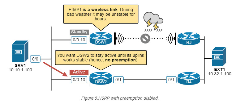
In normal circumstances, DSW1 is the active router and tracks its uplink. However, the uplink is a wireless link. During bad weather such as lighting storm, the wireless link can be unstable for hours. In such scenarios, if the uplink flaps and triggers a switchover to the other router, you don’t want DSW1 to become active again after the uplink recovers because it will likely flap again and trigger another switchover and then again and again for hours.
The network will be much more stable if we do not use preemption in this case. When DSW1’s uplink flaps the first time and triggers a switchover, DSW2 will take over and remain the active router until a manual intervention by the network admin or its uplink goes down.
Keep in mind that if you are using tracking without preemption, you cannot use the standby 10 track 10 decrement 50 command because decrementing the priority won’t trigger a switchover (because preemption is disabled). That’s why there is another tracking option – shutdown, as shown in the output below.
DSW1(config-subif)# standby 10 track 10 ?
decrement Priority decrement
shutdown Shutdown group
<cr>
What is VRRP?
Hosts on the LAN, such as servers, PCs, laptops, mobile phones, etc., typically have a single default gateway address. This introduces a single point of failure in the network. If the default gateway becomes unavailable, the hosts can only communicate within their local LAN and lose access to the rest of the network. Similarly to HSRP, VRRP provides a solution to this problem.
VRRP allows multiple routers to operate as a single virtual router, which hosts can then use as their default gateway.
At first glance, you can notice a few major differences between VRRP and HSRP, as shown in the diagram above.
When the virtual router address uses R1’s physical interface’s IP address, R1 assumes the role of the master virtual router and is also known as the IP address owner. As the master virtual router, R1 controls the virtual router IP address 10.1.1.1 and is responsible for forwarding packets sent to this IP address.
R2 functions as a backup virtual router. If the master virtual router fails, the backup router becomes the master virtual router and provides uninterrupted service for the LAN hosts. In VRRP, preemption is enabled by default. When R1 recovers, it becomes the master virtual router again.
The history of VRRP
HSRP and VRRP were introduced at the same time in the 1990s when organizations started relying heavily on their corporate networks. Cisco identified the need for first-hop router redundancy but, in the absence of a standards-based solution, developed HSRP as a proprietary protocol. Later, the IETF introduced VRRP, which offers similar features but as an open-standard protocol.
VRRP provides the same functionality as HSRP. Both protocols aim to offer redundancy for hosts’ default gateway and optional preemption.
Versions
The protocol has evolved into three major versions: VRRPv1, VRRPv2, and VRRPv3. However, Version 1 is now completely obsolete and not supported by modern network devices. It has been completely replaced by VRRPv2 and VRRPv3 for enhanced features and security. The following table compares the two modern versions
| Feature | VRRPv2 | VRRPv3 |
| IP Protocol Support | Only IPv4 | IPv4 and IPv6 |
| Authentication | Does not support authentication | IPsec-based authentication |
| Multicast address | Uses 224.0.0.18 for IPv4 | Uses 224.0.0.18 for IPv4 and FF02::12 for IPv6 |
| Priority | 1–255, where higher is better | 1–255, where higher is better |
| Virtual MAC address | 0000.5E00.01xx for IPv4 | 0000.5E00.01xx for IPv4 and 0000.5E00.02xx for IPv6 |
| RFC | RFC3768 | RFC5798 |
In summary, VRRPv3 is an improvement over VRRPv2. It primarily adds support for IPv6 and enhances security with IPsec authentication. In this lesson, when we say “VRRP,” we refer to VRRPv3.
VRRPv3 vs HSRPv2
The following table compares the differences between the most modern versions of HSRPv2 and VRRPv3.
| HSRP | VRRP | |
| Cisco-propriatary | Yes | No (open standard) |
| The virtual IP must be different from routers’ physical IPs? | Yes | No |
| Preemption disabled by default | Yes | No |
| Supports IPv4 and IPv6 | Yes | Yes |
| Multicast address | 224.0.0.102 | 224.0.0.18 |
| Virtual MAC | 0000.0c9f.fxxx | 0000.5e00.01xx |
| Max group numbers supported | 4096 (0-4095) | 255 (1-255) |
| Transport | UDP/1985 | IP/112 |
| Default Hello timer | 3 seconds | 1 second |
In summary, the essential difference is that HSRP is Cisco-proprietary, while VRRP is open-standard. You can safely use either one as a first-hop redundancy protocol and have a resilient default gateway. Typically, the design choice of which one to use depends on the type of network equipment. If the network is 100% Cisco-based, you use HSRP. If it is another vendor, you use VRRP.
VRRP Concept
Now, let’s zoom into VRRP a little bit more and examine the most fundamental aspects of the protocol.
Basic Configuration
Let’s start with the basic configuration. Although it is not part of the CCNA blueprint, knowing how to configure the protocol helps a lot in understanding how it works. The following diagram shows the most basic configuration setup
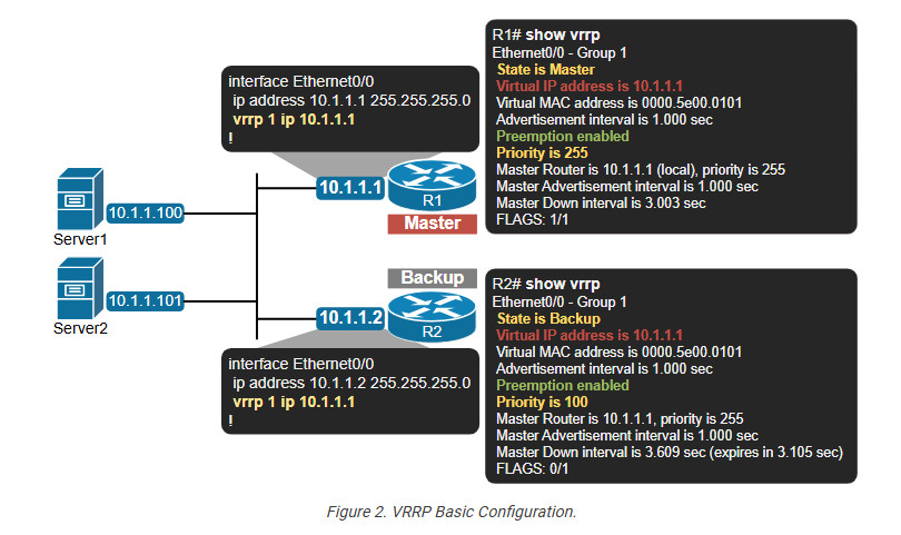
Notice that similarly to HSRP, VRRP is configured per interface. The basic command that enables the protocol always starts with vrrp [VRID], where VRID is the virtual router identifier. This is the analog of the HSRP group number. It is a number in the range between 1 and 255 and there is no default value. It must be explicitly set.
Also, notice that the virtual router IP address can be the IP address of the physical interface of R1. This is not possible with HSRP, where the VIP must be a different IP than the physical interfaces’ IP addresses.
When the VRRP VIP is configured, as shown in the output below, the router is called “IP owner” because its IP address 10.1.1.1 is configured as virtual router address 10.1.1.1.
R1# show run interface e0/0
interface Ethernet0/0
ip address 10.1.1.1 255.255.255.0
vrrp 1 ip 10.1.1.1
end
This configuration simplifies the Master/Backup election process, as you can see in the next section of the lesson.
The election process
The VRRP Master/Backup election process is based on priority. The priority value is between 0 and 255, where 100 is the default value. If there is a tie, the highest IP address wins.
There are two special priority values that cannot be configured explicitly with the vrrp 1 priority [value] command, 0 and 255
The values from 1 to 254 are available for explicit configuration on VRRP routers, as you can see in the output below.
R1(config-if)# vrrp 1 priority ?
<1-254> Priority level(default 100)
Higher values indicate higher priority and a higher likelihood of becoming the master virtual router. The default priority value is 100 (same as HSRP).
Timers
In VRRP, only the Master virtual router sends periodic VRRP advertisement packets (Hellos) to indicate its availability and status. The advertisement timer is 1 second by default. (In HSRP, it is 3 seconds by default). The advertisements are encapsulated in IP/112 and sent to the VRRP link-local multicast address 224.0.0.18.
Backup routers simply listen for these advertisements from the Master. If a backup router does not receive 3xAdvertisements from the Master within a specific timeout period (Master Down Interval), it assumes the Master has failed. The backup routers then initiate an election process to select a new Master based on their priority values.
Preemption
Preemption is enabled by default in VRRP. This is a big difference from HSRP, where preemption is disabled by default.
Notice in the output below that we haven’t configured preemption explicitly, but it is enabled by default.
R1# show run int e0/0
interface Ethernet0/0.20
encapsulation dot1Q 20
ip address 10.1.1.1 255.255.255.0
vrrp 1 ip 10.1.1.1
!
R1# show vrrp
Ethernet0/0 - Group 1
State is Master
Virtual IP address is 10.1.1.1
Virtual MAC address is 0000.5e00.0101
Advertisement interval is 1.000 sec
Preemption enabled
Priority is 255
Master Router is 10.1.1.1 (local), priority is 255
Master Advertisement interval is 1.000 sec
Master Down interval is 3.003 sec
FLAGS: 1/1
Use Cases
The Virtual Router Redundancy Protocol is commonly used in the same scenarios where we use HSRP or any other first-hop redundancy protocol. The most common use cases include:
The design choice when to use VRRP instead of HSRP is primarily based on the network equipment vendor. In Cisco environments, engineers prefer to use HSRP. In non-Cisco environments, VRRP is the only standard choice for first-hop redundancy.
If you are studying for the CCNA (200-301) v1.1 exam, you don’t need to know VRRP in great detail. However, if you plan to follow a path as a network engineer, it is a good starting point for practicing configuring VRRP in the same topology that we used for HSRp in the previous lesson. You can download the EVE-NG initial topology from the section below.
Gateway Load Balancing Protocol (GLBP)
The Gateway Load Balancing Protocol (GLBP) is the last first-hop redundancy protocol (FHRP) we discuss in this section. It serves the same function as the HSRP and VRRP—it provides redundancy for the default gateway. However, GLBP supports load balancing, while HSRP and VRRP only support load sharing.
HSRP/VRRP Load Sharing
To provide context around this lesson and understand why Cisco has introduced GLBP, let’s discuss the difference between load sharing and load balancing.
Load Sharing refers to distributing traffic across multiple routers based on predefined static configuration. For example, we have a subnet with many hosts and two routers running HSRP. Suppose we want to load balance the traffic between the two local routers. Since HSRP does not support true load balancing, the only way to achieve it is to configure two different HSRP groups (say groups 1 and 2) and make a different router Active for each group. For example, R1 is the Active router for HSRP group 1, and R2 is the active group for HSRP group 2.
However, this is still not enough. We also need to configure one-half of the hosts with a default gateway pointing to HSRP 1’s VIP and the other half of the hosts with a default gateway pointing to HSRP 2’s VIP, as shown in the diagram below.
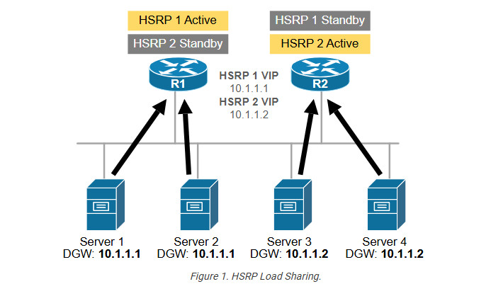
The load-sharing process involves configuring different default gateways on hosts and multiple HSRP groups per subnet. This becomes problematic at scale. That’s why HSRP/VRRP load sharing is typically not used in large-scale networks.
Load Balancing refers to the process of dynamically distributing traffic evenly across multiple routers based on real-time conditions without requiring different default gateway addresses on different hosts on the local network. HSRP and VRRP support only load-sharing, as shown in the diagram above. That’s why Cisco introduced another first-hop redundancy protocol specially designed to perform true load balancing – the Gateway Load Balancing Protocol (GLBP).
GLBP is the only protocol that can do proper load-balancing inside one virtual router group, as shown in the diagram above. Now, let’s see how.
What is GLBP?
GLBP is a first-hop redundancy protocol (FHRP) that provides redundancy for the default gateway router, similar to HSRP and VRRP. However, the main improvement that GLBP provides compared to HSRP/VRRP is that it supports proper load balancing. Look at the diagram below and compare it to Figure 1 above.
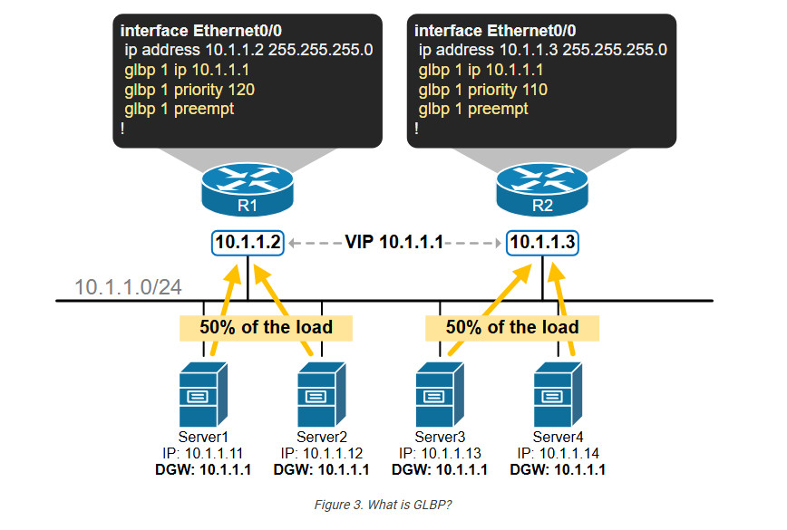
You can see that host traffic is equally load-balanced between the two local routers. However, let’s highlight the big differences compared to the HSRP/VRRP load sharing:
These improvements make GLBP much more efficient at scale if the organization wants to load balance the default gateway traffic. Let’s now zoom in and see how it works.
How does GLBP work?
GLBP works per subnet as all other FHRP protocols. When there are multiple GLBP routers on the same subnet, they must be configured with the same group number, the same virtual address, and different priorities, as shown in the output below (similarly to HSRP):
interface Ethernet0/0
glbp [group] ip [virtual address]
glbp [group] priority [priority value]
Then, based on the configured priority values, all routers in the GLBP group elect the one with the highest priority to act as the Active Virtual Gateway (AVG). In a tie, the router with the highest IP address wins. The router with the second highest priority is elected as the standby router.
There is only one AVG per GLBP group. The function of the AVG router is to assign a virtual MAC address to each other member of the GLBP group. Once a router is assigned a virtual MAC address, it becomes an Active Virtual Forwarder (AVF).
When a host sends an ARP request, the AVG responds with one of the virtual MAC addresses from the available AVFs. This mechanism ensures that different hosts have different VIP-to-VMAC bindings, which load balances the traffic among the GLBP routers in the group.
This is a high-level overview of how GLBP works. Now, let’s zoom in a little bit more.
GLBP Control-plane
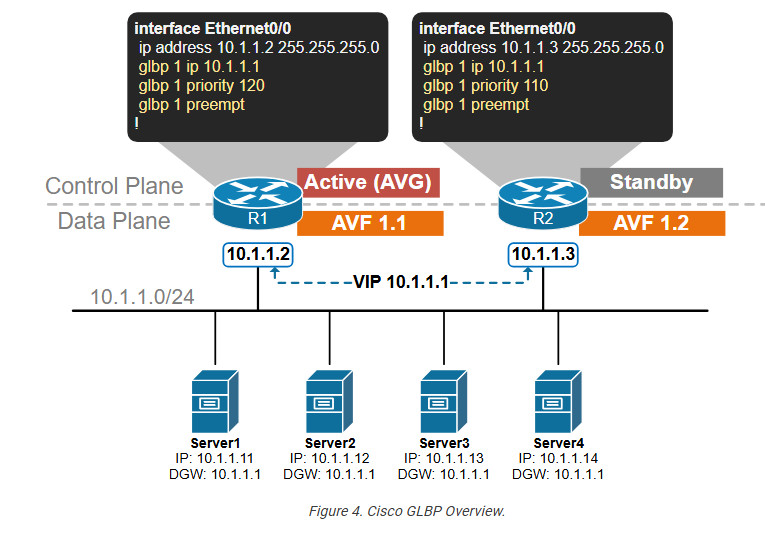
Let’s introduce a more complex topology with three local routers (R1, R2, and R3) connected to subnet 10.1.1.0/24 and several servers (Server 1 through 6). All servers are confirmed with a default gateway address of 10.1.1.1. The routers are configured as shown below
R1(config)# interface Ethernet0/0
glbp 1 ip 10.1.1.1
glbp 1 priority 120

R2(config)# interface Ethernet0/0
glbp 1 ip 10.1.1.1
glbp 1 priority 110

R3(config)# interface Ethernet0/0
glbp 1 ip 10.1.1.1
glbp 1 priority 100
Now, let’s break down the GLBP control-plane operation into three main steps and then see how the server’s traffic is load-balanced across the three local routers in the data plane.
Step 1. Electing an Active Virtual Gateway (AVG)
When GLBP is configured on a router interface, the router starts exchanging hello messages to announce its presence on the subnet and share its priority and IP information. The Hello messages are sent to the link-local multicast address 224.0.0.102 using UDP port 3222.
The router with the highest priority becomes the Active Virtual Gateway (AVG). The router with the second-highest priority (or IP address) becomes the standby router. It monitors the AVG and takes over if the current AVG fails.
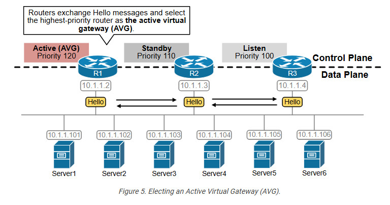
For example, R1 has the highest priority (120), so it becomes the AVG for the group. R2 has the second highest priority (110), so it becomes the standby router. R3 then acts as a backup in case any of the active/standby routers fail.
Let’s look at the CLI representation of the election process. The first line in the show glbp brief output shows the router’s control-plane state based on the configured priority and the election process.
R1# show glbp brief
Interface Grp Fwd Pri State Address Active router Standby router
Et0/0 1 - 120 Active 10.1.1.1 local 10.1.1.3
Et0/0 1 1 - Active 0007.b400.0101 local -
Et0/0 1 2 - Listen 0007.b400.0102 10.1.1.3 -
Et0/0 1 3 - Listen 0007.b400.0103 10.1.1.4 -

R2# show glbp brief
Interface Grp Fwd Pri State Address Active router Standby router
Et0/0 1 - 110 Standby 10.1.1.1 10.1.1.2 local
Et0/0 1 1 - Listen 0007.b400.0101 10.1.1.2 -
Et0/0 1 2 - Active 0007.b400.0102 local -
Et0/0 1 3 - Listen 0007.b400.0103 10.1.1.4 -

R3# show glbp brief
Interface Grp Fwd Pri State Address Active router Standby router
Et0/0 1 - 100 Listen 10.1.1.1 10.1.1.2 10.1.1.3
Et0/0 1 1 - Listen 0007.b400.0101 10.1.1.2 -
Et0/0 1 2 - Listen 0007.b400.0102 10.1.1.3 -
Et0/0 1 3 - Active 0007.b400.0103 local
Notice that R1 is the Active Virtual Gateway (AVG) for GLBP group 1 with a priority of 120. R2 is elected the Standby router with priority 110. R3 is in a Listen to state, meaning it waits to become Active or Standby in case R1/R2 fails.
Step 2. Assigning a Virtual MAC to members
Once the AVG router has been elected, it assigns a virtual MAC address to every group member through Hello Request/Response messages. Once a member is assigned a virtual MAC, it becomes an Active Virtual forwarder (AVF) for that virtual MAC address, as shown in the diagram below.
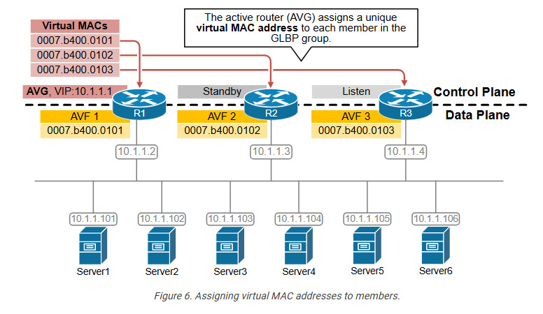
Let’s look at the CLI representation of this concept. Notice that R1 is the Active Forwarder for the first virtual MAC address. R2 is the AVF for the second virtual MAC address, and R3 is active for the third.
R1# show glbp brief
Interface Grp Fwd Pri State Address Active router Standby router
Et0/0 1 - 120 Active 10.1.1.1 local 10.1.1.3
Et0/0 1 1 - Active 0007.b400.0101 local -
Et0/0 1 2 - Listen 0007.b400.0102 10.1.1.3 -
Et0/0 1 3 - Listen 0007.b400.0103 10.1.1.4 -

R2# show glbp brief
Interface Grp Fwd Pri State Address Active router Standby router
Et0/0 1 - 110 Standby 10.1.1.1 10.1.1.2 local
Et0/0 1 1 - Listen 0007.b400.0101 10.1.1.2 -
Et0/0 1 2 - Active 0007.b400.0102 local -
Et0/0 1 3 - Listen 0007.b400.0103 10.1.1.4 -

R3# show glbp brief
Interface Grp Fwd Pri State Address Active router Standby router
Et0/0 1 - 100 Listen 10.1.1.1 10.1.1.2 10.1.1.3
Et0/0 1 1 - Listen 0007.b400.0101 10.1.1.2 -
Et0/0 1 2 - Listen 0007.b400.0102 10.1.1.3 -
Et0/0 1 3 - Active 0007.b400.0103 local
Notice that GLBP uses the MAC address format shown below. The group number in blue represents the configured group in HEX. The AFV number represents the forwarder number in HEX.
There can be up to four virtual MAC addresses per group. Hence, there can be up to four active forwarders per group.
Step 3. Answering hosts’ ARP requests
The last piece of the puzzle that glues everything together is the Address Resolution Process (ARP) that every host on the subnet uses to resolve the MAC address of its default gateway. When a host sends an ARP Request for the VIP 10.1.1.1, the AVG router responds to the request with the first virtual MAC address 0007.b400.0101. When another host sends an ARP request, the AVG responds with the next MAC address, 0007.b400.0102. When another host ARPs, the AVG responds with 0007.b400.0103, and so on. The AVG answers to ARP with different virtual MAC addresses in a round-robin manner.
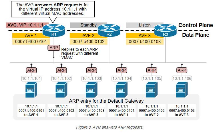
In the end, each server has a different ARP entry for the default gateway address, as shown in the diagram above.
Data plane
After the control plane operation is completed, every host in the local network receives an ARP response with a different AVF MAC address for the default gateway. Recall that at the Ethernet layer, data packets (called frames) are sent directly to the destination MAC address based on the ARP table. Since every host has different IP-to-MAC binding for the default gateway, the traffic is balanced between the three active virtual forwarders (AVF), as shown in the diagram below.
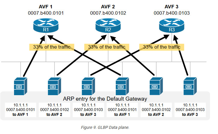
For example, the first server has the binding 10.1.1.1 – 0007.b400.0101 for the default gateway. Therefore, it sends all traffic destined for external networks to destination MAC 0007.b400.0101, which goes to R1.
On the other hand, the second server has the binding 10.1.1.1 – 0007.b400.0102 for the default gateway. Therefore, it sends all traffic destined for external networks to destination MAC 0007.b400.0102, which goes to R2.
The third server has the binding 10.1.1.1 – 0007.b400.0103 for the default gateway. Therefore, it sends all traffic destined for external networks to destination MAC 0007.b400.0103, which goes to R3, and so on.
GLBP Key Takeaways
GLBP is a Cisco proprietary tool that takes HSRP and VRRP to the next level (or so I though it would). In addition to providing first hop redundancy, it also provides a load balancing mechanism for the clients. That is, all routers in the group are active at all times. As with HSRP and VRRP, routers that are to participate in GLBP must be a member of the same group. Once the routers are part of the same group, they elect one router to be the AVG (Active Virtual Gateway). The AVG is elected based on highest priority which then falls back to highest IP if the priorities match. Up to 4 routers total can be in the same GLBP group. One is the AVG, and up to 3 others can be AVFs (Active Virtual Forwarders). The 4 router limit only applies to routers that will actively forward traffic. If a 5th (or higher number) router joins the group it will become a SVF (Standby Virtual Forwarder) and will take the place of a AVF in case of failure. There is also a SVG (Standby Virtual gateway) role as well.
GLBP balances traffic by having the AVG assign each AVF virtual MAC addresses. When the GLBP group sees a ARP request come in for the virtual IP, the AVG responds to the clients ARP request with one of the AVF’s virtual MACs.
Note: I’ll note here that some documentation I’ve found uses the SVF term to describe a router that is above and beyond the 4 router AVF limit and is waiting to join the group (the way I use it). Other documentation uses SVF to describe an active AVF that is ready to take over another AVFs role in case of failure. That is, router1 is a SVF for routers 2,3,4 and 5.
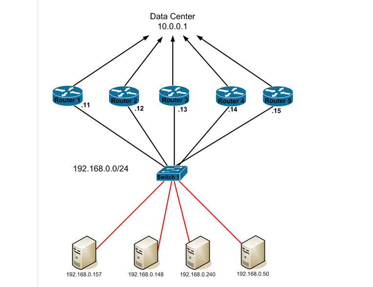
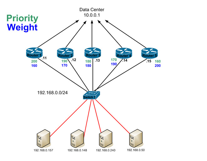
In this example, we have 5 GLBP routers. Let’s put the bare minimum GLBP config on each router and examine what occurs. On each router, we’ll run this command to enable GLBP…

Router#config t
Enter configuration commands, one per line. End with CNTL/Z.
Router(config)#int fa0/0
Router(config-if)#glbp 5 ip 192.168.0.1
Router(config-if)#

This tells the router that it should be part of GLBP group 5 which has a virtual IP of 192.168.0.1. Once we have that configured on each router, let’s take a look at the ‘show glbp’ output on Router 5…

Router5#show glbp
FastEthernet0/0 – Group 5
State is Active
1 state change, last state change 00:05:38
Virtual IP address is 192.168.0.1
Hello time 3 sec, hold time 10 sec
Next hello sent in 1.856 secs
Redirect time 600 sec, forwarder timeout 14400 sec
Preemption enabled, min delay 0 sec
Active is local
Standby is 192.168.0.14, priority 100 (expires in 9.920 sec)
Priority 100 (default)
Weighting 100 (default 100), thresholds: lower 1, upper 100
Load balancing: round-robin
Group members:
0013.19d7.6990 (192.168.0.12)
0018.19f3.86fa (192.168.0.11)
001d.704c.0dac (192.168.0.13)
0021.a009.993c (192.168.0.14)
0021.a0f1.61fc (192.168.0.15) local
There are 4 forwarders (1 active)
Forwarder 1
State is Listen
4 state changes, last state change 00:04:40
MAC address is 0007.b400.0501 (learnt)
Owner ID is 0013.19d7.6990
Redirection enabled, 597.888 sec remaining (maximum 600 sec)
Time to live: 14397.888 sec (maximum 14400 sec)
Preemption enabled, min delay 30 sec
Active is 192.168.0.12 (primary), weighting 100 (expires in 8.224 sec)
Client selection count: 1
Forwarder 2
State is Active
1 state change, last state change 00:05:08
MAC address is 0007.b400.0502 (default)
Owner ID is 0021.a0f1.61fc
Redirection enabled
Preemption enabled, min delay 30 sec
Active is local, weighting 100
Forwarder 3
State is Listen
MAC address is 0007.b400.0503 (learnt)
Owner ID is 001d.704c.0dac
Redirection enabled, 597.408 sec remaining (maximum 600 sec)
Time to live: 14397.408 sec (maximum 14400 sec)
Preemption enabled, min delay 30 sec
Active is 192.168.0.13 (primary), weighting 100 (expires in 8.384 sec)
Forwarder 4
State is Listen
MAC address is 0007.b400.0504 (learnt)
Owner ID is 0021.a009.993c
Redirection enabled, 597.760 sec remaining (maximum 600 sec)
Time to live: 14397.760 sec (maximum 14400 sec)
Preemption enabled, min delay 30 sec
Active is 192.168.0.14 (primary), weighting 100 (expires in 8.288 sec)
Router5#

Let’s dissect this output piece by piece and talk about what it means.

The top portion of the output talks about the who the AVG is, as well as the general state of the group.

FastEthernet0/0 – Group 5
State is Active

The first line tells about the group we are looking at as well as the interface that GLBP is running on. The second line tells us that this router in the Active AVG. Why is this router the active AVG? Since we haven’t configured the priority yet, GLBP picks the router with the highest IP address to be the active AVG. If we look at the other 5 routers this is what we see…

router1#show glbp brief
Interface Grp Fwd Pri State Address Active router Standby router
Fa0/0 5 – 100 Listen 192.168.0.1 192.168.0.15 192.168.0.14
<additional output not shown>

router2#show glbp brief
Interface Grp Fwd Pri State Address Active router Standby router
Fa0/0 5 – 100 Listen 192.168.0.1 192.168.0.15 192.168.0.14
<additional output not shown>

router3#show glbp brief
Interface Grp Fwd Pri State Address Active router Standby router
Fa0/0 5 – 100 Listen 192.168.0.1 192.168.0.15 192.168.0.14
<additional output not shown>

router4#show glbp brief
Interface Grp Fwd Pri State Address Active router Standby router
Fa0/0 5 – 100 Standby 192.168.0.1 192.168.0.15 local
<additional output not shown>

So all the other routers know who the AVG is as well as who the SVG is. Router4 is the SVG so he marks himself as ‘local’ under the Standby router field…

1 state change, last state change 00:05:38
Virtual IP address is 192.168.0.1
Hello time 3 sec, hold time 10 sec
Next hello sent in 1.856 secs
Redirect time 600 sec, forwarder timeout 14400 sec
Preemption enabled, min delay 0 sec
Active is local
Standby is 192.168.0.14, priority 100 (expires in 9.920 sec)
Priority 100 (default)
Weighting 100 (default 100), thresholds: lower 1, upper 100
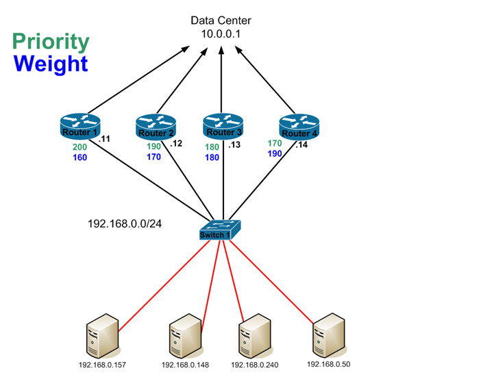
The next chunk of output gives us some general information about the local GLBP host as well as the group in general. We can see the virtual IP that the group is responsible for which was configured on all of the hosts to star the GLBP process. We can also see the local priority of this GLBP host. Note that it’s set to 100. As the output, states this is the default value. The priority is used to determine who the active AVG is. The router with the highest AVG will always be the AVG, and the second highest will always be the SVG. Let’s take a look at this by enabling GLBP preemption on the hosts and changing the priorities of all the routers…
Router1
interface FastEthernet0/0
glbp 5 priority 200
glbp 5 preempt

Router2
interface FastEthernet0/0
glbp 5 priority 190
glbp 5 preempt

Router3
interface FastEthernet0/0
glbp 5 priority 180
glbp 5 preempt

Router4
interface FastEthernet0/0
glbp 5 priority 170
glbp 5 preempt

Router5
interface FastEthernet0/0
glbp 5 priority 160
glbp 5 preempt
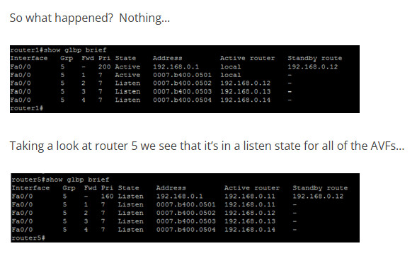
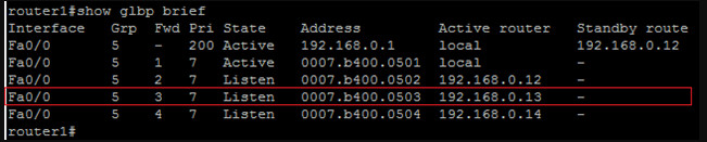
Now let’s take a look at the output of the ‘show glbp brief’ command on rouer1…
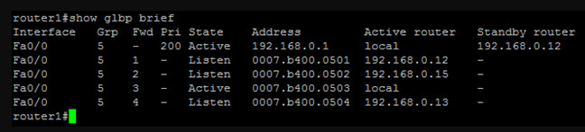
As you can see, router1 is now the active AVG with router 2 (with the second highest priority) being the SVG. Let’s take a second to talk about the output from this command.
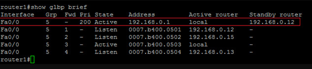
The first line in the output talks about the group in general. It tells you the priority of the AVG, the GLBP group IP, the AVG and the SVG. In this case, the priority of the AVG is 200, the group IP is 192.168.0.1, the AVG is local, and the SVG is router2.
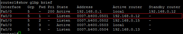
The second line talks about the first AVF in the group. The meaning of the ‘state’ column changes here slightly. As far as router1 is concerned, it is listening to this AVF to make sure that it is still online. This does NOT imply that this AVF is not active. This is just the view point from router1. The rest of the line shows the virtual MAC that this AVF is responsible for as well as the router’s IP address.
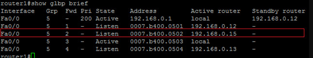
The third line talks about the second virtual forwarder. Again, from router1’s perspective it is listening to this AVF. We see the virtual MAC that this AVF is using and responsible for as well as it’s IP address.
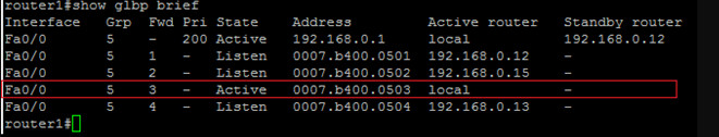
warder. The state is shown as active here since the third AVF is the local router itself. This shows that a router can own both the AVG as well as the AVF roles. We see the virtual MAC as well as ‘local’ to indicate that this router has this role.
The fifth line shows the forth AVF, it’s virtual MAC and IP address.
The remainder of the initial ‘show glbp’ output talks about the load balancing method used as well as the forwarders. Let’s spend some time talking about the AVFs and then talk about load balancing methods.
You might be wondering how the AVFs are picked. You might have noticed that after we changed the AVG by manipulating the priorities, that we ended up with this..
AVG – Router1
SVG – Router2
AVFs…
Router1
Router2
Router3
Router5
So what happened to router4? Why isn’t it being used as an AVF? The answer is hard to come by but I can tell you you what I’ve discerned from testing this in my lab.
The decision of which routers should be AVFs is based on weight. Moreover, it appear to be based on the order in which routers join the group. While it’s quite easy to move the AVG and SVG around, moving a router from being an AVF or SVF is considerably harder to do. Let’s first start by talking about weight. Some documentation I’ve read indicates that the weight is what’s used to determine which router’s will be AVFs and which will be SVFs. Additionally, AVF/SVF preemption is a default setting in GLBP. The AVFs or SVFs will preempt automatically with a 30 second delay. This all being said, one would assume that you could set the weights in the same fashions that we set the priorities and move the AVF and SVF roles around. That’s not the case. It appears that AVF preemption doesn’t actually exist.
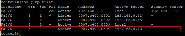
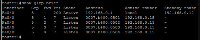
Let’s start by looking at this example. As stated, it’s pretty easy to move the AVG role around with priorities, so it’s easy to tell here the router1 is the AVG and router2 is the SVG based on their active priorities. Since we have 4 router’s here, it’s safe to say that each one of the these routers will successfully claim and AVF role since we can have a max of 4. Let’s take a look and verify…
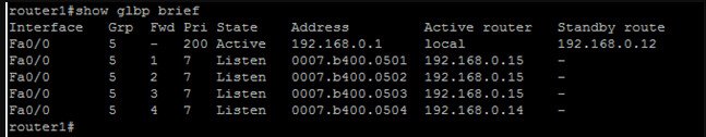
As we can see, all 4 of the routers have an AVF role as we expected. Now, let’s add the 5th router in with a priority of 160 and a weight of 200. With a weight of 200, we can very easily assume that it will take one of the AVF roles from one of the other routers. Let’s see what happens…
At this point, it’s pretty easy to see that AVF’s don’t really preempt each other in regards to the assigned weight. If they did, then router5 would have taken any of the other 4 routers AVF role.
The other way to use weight is to determine if the AVF is a feasible forwarder. That is, if it should even be forwarding packets. This is done using the same tracking method we saw in HSRP and VRRP. Additionally, when you configure the weight of a router, you also configure it’s upper and lower limits. The upper and lower limits dictate when a AVF should and shouldn’t be an AVF. For instance, let’s look at this configuration on router1…
track 1 interface Loopback0 line-protocol

interface Loopback0
ip address 1.1.1.1 255.255.255.255
interface FastEthernet0/0
ip address 192.168.0.11 255.255.255.0
duplex auto
speed auto
glbp 5 ip 192.168.0.1
glbp 5 timers redirect 60 660
glbp 5 priority 200
glbp 5 preempt
glbp 5 weighting 160 lower 150 upper 155
glbp 5 weighting track 1 decrement 15
For now, focus just on the bolded lines. This configuration says that the router should have a weight of 160. If the weight falls below the lower limit of 150, then we should take away it’s AVF role. When the weight once again returns to be equal or above the upper limit of 155, we can give it the AVF role back. We are also telling the router to track interface loop0 on the line protocol. If loop0 goes down, decrement the weight by 15.
I have placed a similar configuration on each of the 5 router’s with the following weights…
Router1
glbp 5 weighting 160 lower 150 upper 155

Router2
glbp 5 weighting 170 lower 160 upper 165

Router3
glbp 5 weighting 180 lower 170 upper 175

Router4
glbp 5 weighting 190 lower 180 upper 185

Router5
glbp 5 weighting 200 lower 190 upper 195
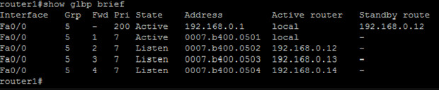
So let’s shutdown loop0 on router1 and see what happens. On router 1 we see…
*Jan 6 21:16:45.955: GLBP: Fa0/0 5 Track 1 object changed, state Up -> Down
*Jan 6 21:16:45.955: GLBP: Fa0/0 5 Weighting 160 -> 145
*Jan 6 21:16:47.955: %LINK-5-CHANGED: Interface Loopback0, changed state to administratively down
*Jan 6 21:16:48.955: %LINEPROTO-5-UPDOWN: Line protocol on Interface Loopback0, changed state to down
On all of the other router’s we see…
*Jan 6 21:22:43.011: GLBP: Fa0/0 5.1 Preemption delayed, 30 secs remaining
The preemption delay defaults to 30 seconds and is the time that a router will wait before attempting to preempt a downed AVF. In the end, we see that router5 claims the forwarder 1 position from router1…

Let’s talk briefly about what occurs during an AVF failure. When an AVF fails, another AVF will assume responsibility for the failed AVFs MAC address. That is, it will continue to respond to request for it’s own virtual MAC, as well as the MAC for the failed AVF that it is assuming responsibility for.
Now, let’s quickly talk about two other timers you need to be aware of that handle AVF failure. The first is the redirect timer which dictates how long the AVG will continue to hand the virtual MAC address out to clients. This defaults to 600 seconds. During this time, if the AVF returns to the GLBP group, it will reclaim it’s role as the active AVF and things will resume as they should. If the AVF does not return to the group by the time the redirect timer expires, the AVF that is handling the failed AVFs virtual MAC will continue to do so, but the AVG will no longer hand out the virtual MAC to clients.
The second timer is the forwarder timeout timer. This timer defaults to 14400 seconds and is used to determine when the failed AVF should be entirely flushed from GLBP. When this timer expires, the AVG will take the forwarder out of the GLBP table entirely and revoke the virtual MAC it had been assigned. Let’s take a look at this in action by decreasing the redirect and forwarder timeout values on the AVG. Note, all other AVFs will learn these two timer values from the AVG…
interface FastEthernet0/0
bp 5 timers redirect 60 660
Now, let’s watch and see what happens when the forwarder timeout timer expires for forwarder1. You’ll recall that forwarder 1 had previously been the AVG (router1). We then shut the loopback 0 interface on router1 down which decremented the weight and removed it from being an active AVF. At that point, router5 took router1’s place. If we look at GLBP on router1 we can see that the AVG still thinks that it ‘owns’ the AVF role…
Group members:
0013.19d7.6990 (192.168.0.12)
0013.19d7.aaa4 (192.168.0.15)
0018.19f3.86fa (192.168.0.11) local
001d.704c.0dac (192.168.0.13)
0021.a009.993c (192.168.0.14)
There are 4 forwarders (0 active)
Forwarder 1
State is Listen
4 state changes, last state change 00:06:47
MAC address is 0007.b400.0501 (default)
Owner ID is 0018.19f3.86fa
Redirection enabled
Preemption enabled, min delay 30 sec
Active is 192.168.0.15 (secondary), weighting 200 (expires in 7.432 sec)
Arp replies sent: 1

At this point, we need to wait 11 minutes for the forwarder timeout timer to expire before we see what the AVG does with the role. So after 11 minutes pass, let’s see what happened…

Group members:
0013.19d7.6990 (192.168.0.12)
0013.19d7.aaa4 (192.168.0.15)
0018.19f3.86fa (192.168.0.11) local
001d.704c.0dac (192.168.0.13)
0021.a009.993c (192.168.0.14)
There are 4 forwarders (0 active)
Forwarder 1
State is Listen
4 state changes, last state change 00:11:40
MAC address is 0007.b400.0501 (default)
Owner ID is 0018.19f3.86fa
Redirection enabled
Preemption enabled, min delay 30 sec
Active is 192.168.0.15 (secondary), weighting 200 (expires in 8.684 sec)
Arp replies sent: 1

Again, nothing happened. Why would router1 will still own the forwarder role? Let’s shutdown the loopback interfaces on routers 2 and 3 and see what happens…
And if we look at the forwarders we can see that the owner ID’s are ,for the most part, still listed as the original owners…

Group members:
0013.19d7.6990 (192.168.0.12)
0013.19d7.aaa4 (192.168.0.15)
0018.19f3.86fa (192.168.0.11) local
001d.704c.0dac (192.168.0.13)
0021.a009.993c (192.168.0.14)
There are 4 forwarders (0 active)
Forwarder 1
State is Listen
6 state changes, last state change 00:01:48
MAC address is 0007.b400.0501 (default)
Owner ID is 0018.19f3.86fa
Redirection enabled
Preemption enabled, min delay 30 sec
Active is 192.168.0.15 (secondary), weighting 200 (expires in 7.576 sec)
Forwarder 2
State is Listen
MAC address is 0007.b400.0502 (learnt)
Owner ID is 0013.19d7.6990
Redirection disabled
Time to live: 563.576 sec (maximum 566 sec)
Preemption enabled, min delay 30 sec
Active is 192.168.0.15 (secondary), weighting 200 (expires in 7.576 sec)
Forwarder 3
State is Listen
MAC address is 0007.b400.0503 (learnt)
Owner ID is 0013.19d7.aaa4
Redirection enabled, 57.576 sec remaining (maximum 60 sec)
Time to live: 657.576 sec (maximum 660 sec)
Preemption enabled, min delay 30 sec
Active is 192.168.0.15 (primary), weighting 200 (expires in 7.572 sec)
Forwarder 4
State is Listen
MAC address is 0007.b400.0504 (learnt)
Owner ID is 0021.a009.993c
Redirection disabled
Time to live: 583.976 sec (maximum 585 sec)
Preemption enabled, min delay 30 sec
Active is 192.168.0.15 (secondary), weighting 200 (expires in 8.976 sec)
router1#

Note that the owner for forwarder 3 has changed to the MAC of router5. Why this happened, I can’t be sure but it does seem odd. Nothing from my packet captures or debugs seemed to show why. Also note that the router with the highest IP address will always win a AVF preemption event. This means that we could end up with a scenario like this…
Where you have vey uneven load balancing occurring between AVFs. You’d think that GLBP would have a mechanism in play to level the playing field when something like this occurs.
I also find it interesting that when a router is removed using weight, that it’s never actually pulled from the GLBP table. That is, the AVG still think that the original owner owns the virtual MAC despite the forwarder timeout expiring. If you want to pull a router out of GLBP entirely, you need to completely cut connectivity between the AVG and the AVF. If you do, after the forwarder timeout expires, GLBP will pull the router out of GLBP entirely. If there is another router to take it’s place, that router will take the position. If there’s not, the forwarder count will reduce and the virtual MAC for the legacy forwarder will be removed…
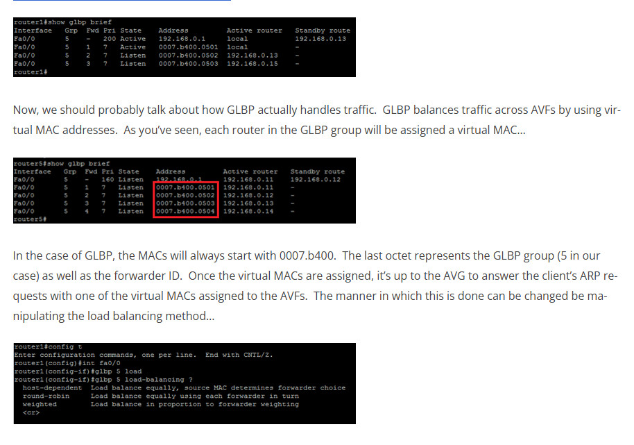
The default load balancing method is round-robin. I think we all know that that is so I won’t explain it. Weighted uses the AVFs defined weight to send proportionate amounts of traffic to a given AVF. Host-dependant ensure that the same virtual MAC is always given to the same client.
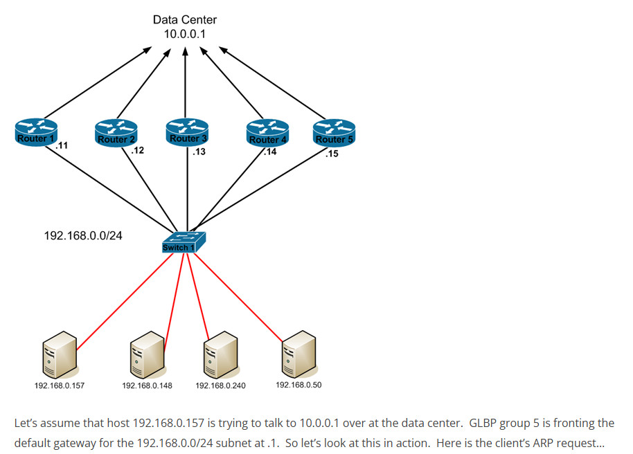
Let’s take a look at what happens when a client tries talking to the GLBP VIP in our original example…
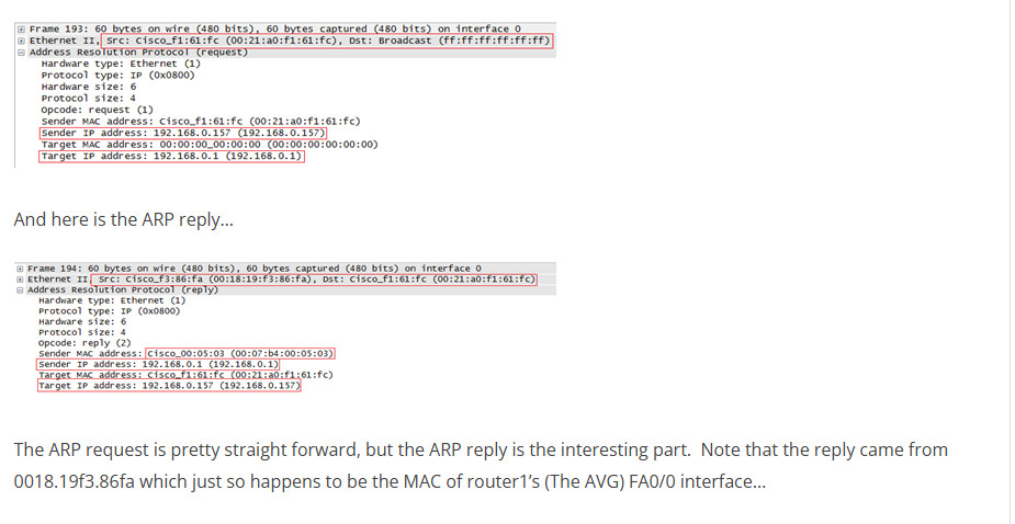
The ARP request is pretty straight forward, but the ARP reply is the interesting part. Note that the reply came from 0018.19f3.86fa which just so happens to be the MAC of router1’s (The AVG) FA0/0 interface…
router1#show int fa0/0
FastEthernet0/0 is up, line protocol is up
Hardware is Gt96k FE, address is 0018.19f3.86fa (bia 0018.19f3.86fa)
Internet address is 192.168.0.11/24
MTU 1500 bytes, BW 100000 Kbit, DLY 100 usec,
reliability 255/255, txload 1/255, rxload 1/255
You can see that the reply contains the MAC address of 0007.b400.0503, the virtual MAC of GLBP forwarder 3…
I’m not going to dig into the other load balancing methods since they are rather straight forward, but I would like to close with some comments on GLBP.
After spending close to a week testing the protocol, I can honestly say I’m not a fan. Here’s why…
-I don’t care for the way that AVFs are elected and that they can’t truly be actively preempted.
-I found through my testing that I wasn’t always receiving the same results. For instance, one time I shut off all of the FA0/0 interfaces on all of the GLBP routers on the switch side (using the interface range command). I then turned them all back on at the same time. Despite having priorities set, router2 became the AVG. There were just too many times that GLBP didn’t do what it should have done.
-The config seems sticky. I ran a couple different code version (12.x and 15.x) and both seemed to experience random GLBP config problems. For instance, there were two different times that a router wouldn’t let me remove the GLBP IP command (glbp 5 ip 192.168.0.1) from an interface. There were even more times that it wouldn’t let me put one on. A reboot always solved the problem.
-It seemed that even when a AVF shouldn’t be forwarding due to a tracked interface failing that it sometimes temporarily came back into the group. No idea why, but I saw it happen several times.
Bottom line, I’m glad I spent the time researching this one. It’s not a protocol I had ever used before in production environments and it certainly operated differently than I had thought it would. I can’t say that I’d ever recommend putting this in anywhere though, too many inconsistencies.