- 8777701917
- info@saikatinfotech.com
- Basirhat W.B

Virtual LAN (VLAN)
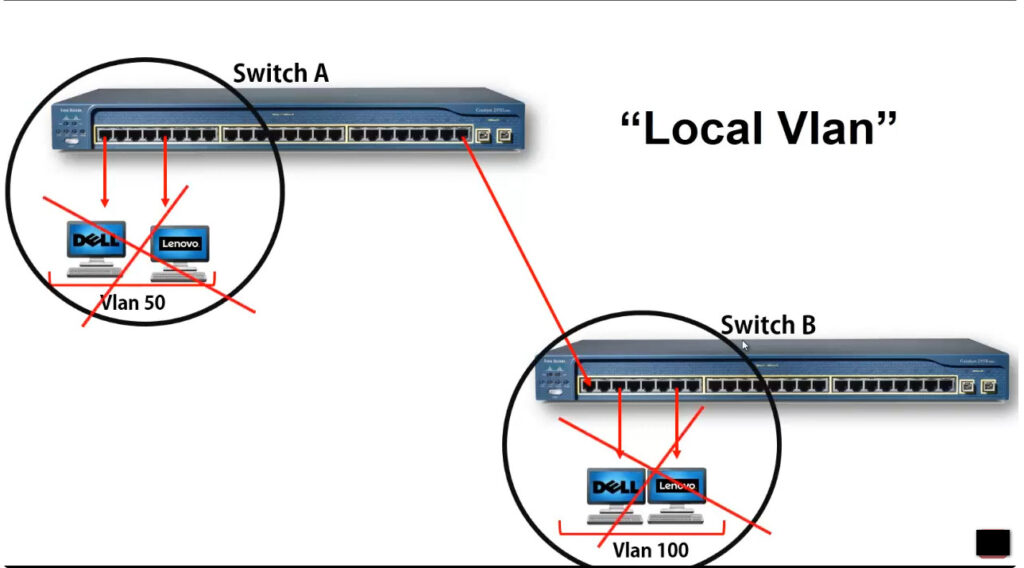
Virtual LAN (VLAN) is a concept in which we can
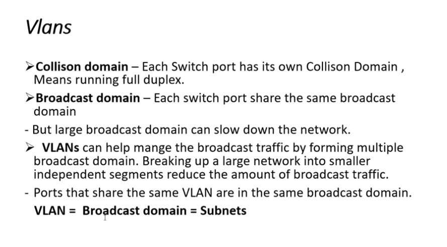
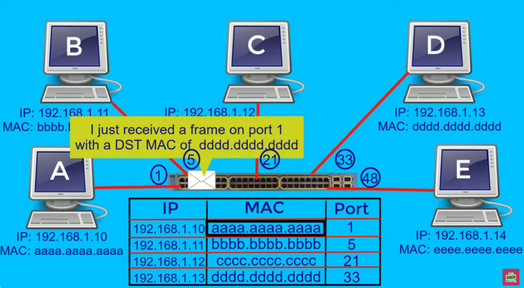
divide the devices logically on layer 2 (data link layer). Generally, layer 3 devices divide the broadcast domain but the broadcast domain can be divided by switches using the concept of VLAN.
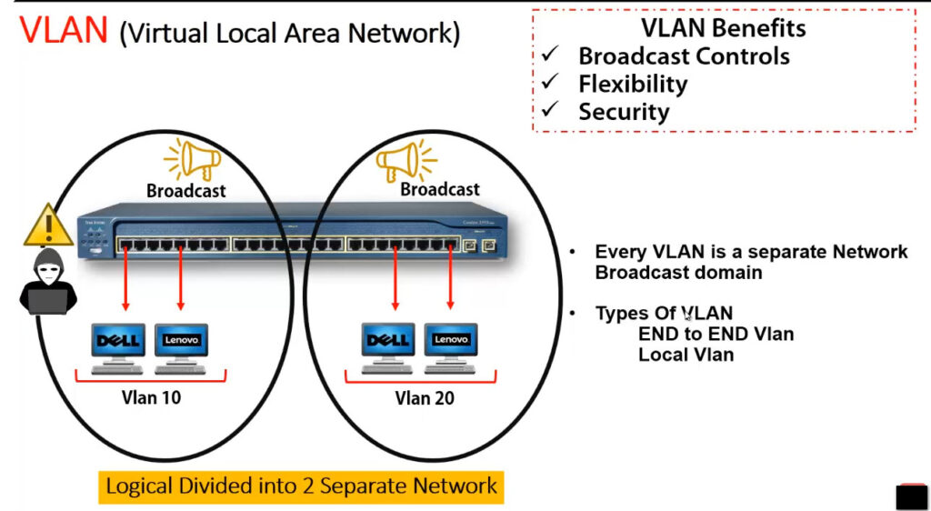
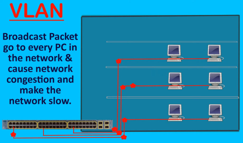
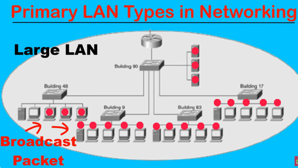
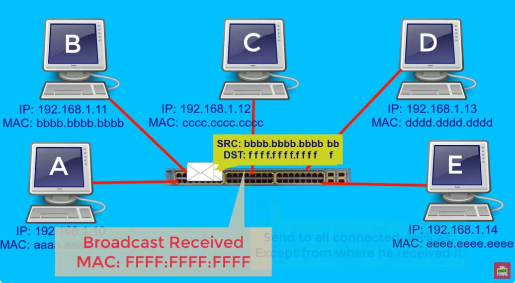
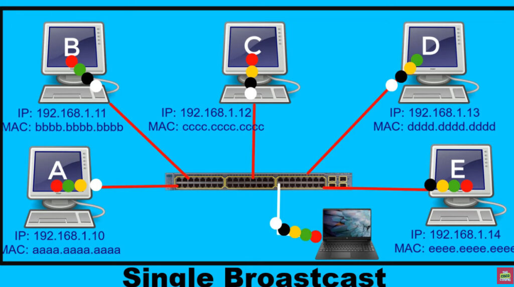
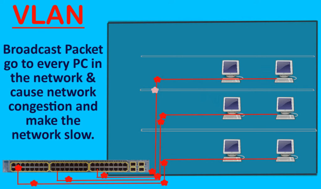
A broadcast domain is a network segment in which if a device broadcast a packet then all the devices in the same broadcast domain will receive it. The devices in the same broadcast domain will receive all the broadcast packets but it is limited to switches only as routers don’t forward out the broadcast packet. To forward out the packets to different VLAN (from one VLAN to another) or broadcast domains, inter Vlan routing is needed. Through VLAN, different small-size sub-networks are created which are comparatively easy to handle.
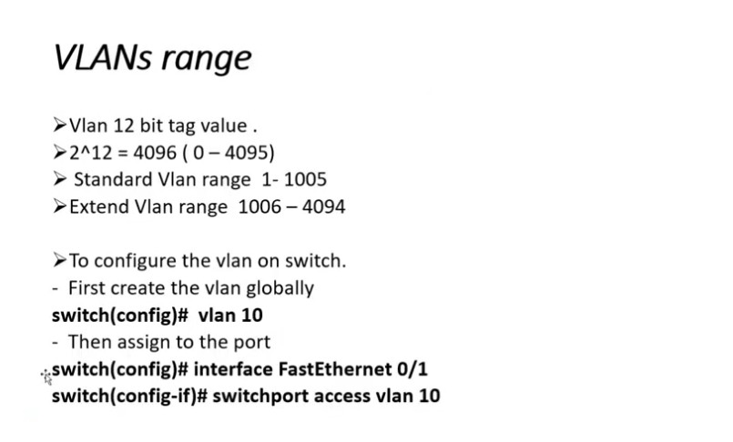
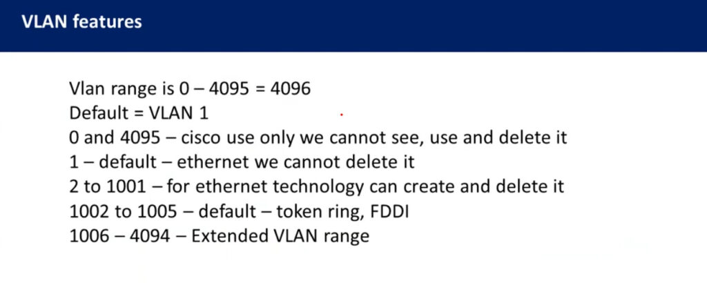
VLAN ranges:
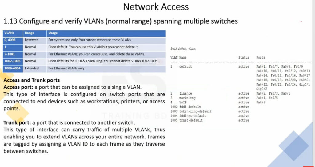
VLAN 0, 4095: These are reserved VLAN which cannot be seen or used.
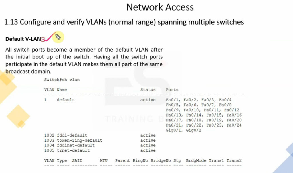
VLAN 1: It is the default VLAN of switches. By default, all switch ports are in VLAN. This VLAN can’t be deleted or edit but can be used.
VLAN 2-1001: This is a normal VLAN range. We can create, edit and delete these VLAN.
VLAN 1002-1005: These are CISCO defaults for fddi and token rings. These VLAN can’t be deleted.
Vlan 1006-4094: This is the extended range of Vlan.
Configuration –
We can simply create VLANs by simply assigning the vlan-id and Vlan name.
#switch1(config)#vlan 2
#switch1(config-vlan)#vlan accounts
Here, 2 is the Vlan I’d and accounts is the Vlan name. Now, we assign Vlan to the switch ports.e.g-
Switch(config)#int fa0/0
Switch(config-if)#switchport mode access
Switch(config-if)#switchport access Vlan 2
Also, switchport range can be assigned to required vlans.
Switch(config)#int range fa0/0-2
Switch(config-if)#switchport mode access
Switch(config-if) #switchport access Vlan 2
By this, switchport fa0/0, fa0/1, fa0-2 will be assigned Vlan 2.
Example –
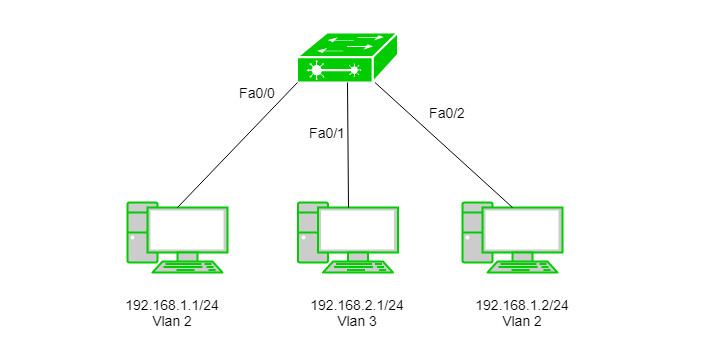
Assigning IP address 192.168.1.1/24, 192.168.1.2/24 and 192.168.2.1/24 to the PC’s. Now, we will create Vlan 2 and 3 on switch.
Switch(config)#vlan 2
Switch(config)#vlan 3
We have made VLANs but the most important part is to assign switch ports to the VLANs.
Switch(config)#int fa0/0
Switch(config-if)#switchport mode access
Switch(config-if) #switchport access Vlan 2
Switch(config)#int fa0/1
Switch(config-if)#switchport mode access
Switch(config-if) #switchport access Vlan 3
Switch(config)#int fa0/2
Switch(config-if)#switchport mode access
Switch(config-if) #switchport access Vlan 2
As seen, we have assigned Vlan 2 to fa0/0, fa0/2, and Vlan 3 to fa0/1.
VLANs offer several features and benefits, including:
Improved network security: VLANs can be used to separate network traffic and limit access to specific network resources. This improves security by preventing unauthorized access to sensitive data and network resources.
Better network performance: By segregating network traffic into smaller logical networks, VLANs can reduce the amount of broadcast traffic and improve network performance.
Simplified network management: VLANs allow network administrators to group devices together logically, rather than physically, which can simplify network management tasks such as configuration, troubleshooting, and maintenance.
Flexibility: VLANs can be configured dynamically, allowing network administrators to quickly and easily adjust network configurations as needed.
Cost savings: VLANs can help reduce hardware costs by allowing multiple virtual networks to share a single physical network infrastructure.
Scalability: VLANs can be used to segment a network into smaller, more manageable groups as the network grows in size and complexity.
Some of the key features of VLANs include:VLAN tagging: VLAN tagging is a way to identify and distinguish VLAN traffic from other network traffic. This is typically done by adding a VLAN tag to the Ethernet frame header.
VLAN membership: VLAN membership determines which devices are assigned to which VLANs. Devices can be assigned to VLANs based on port, MAC address, or other criteria.
VLAN trunking: VLAN trunking allows multiple VLANs to be carried over a single physical link. This is typically done using a protocol such as IEEE 802.1Q.
VLAN management: VLAN management involves configuring and managing VLANs, including assigning devices to VLANs, configuring VLAN tags, and configuring VLAN trunking.
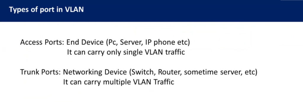
Types of connections in VLAN –
There are three ways to connect devices on a VLAN, the type of connections are based on the connected devices i.e. whether they are VLAN-aware(A device that understands VLAN formats and VLAN membership) or VLAN-unaware(A device that doesn’t understand VLAN format and VLAN membership).
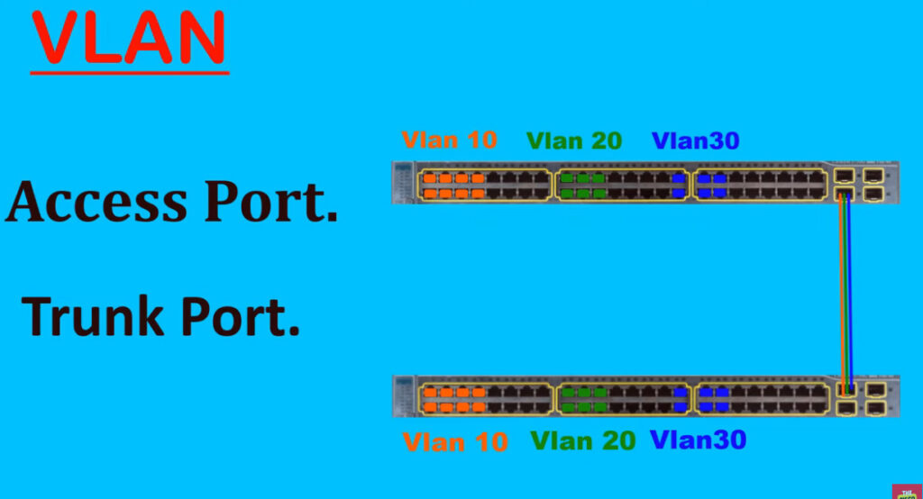
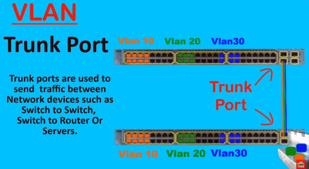
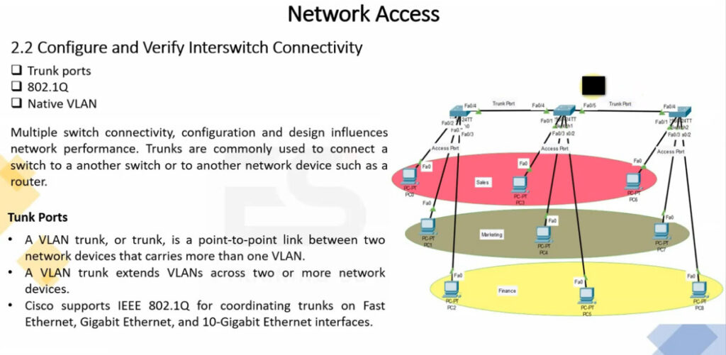
Trunk Link –
All connected devices to a trunk link must be VLAN-aware. All frames on this should have a special header attached to it called tagged frames.
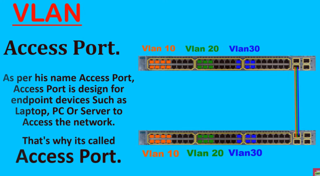
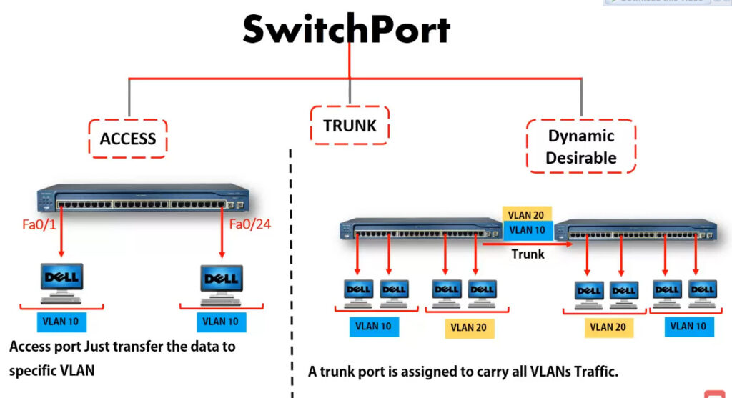
Access link –
It connects VLAN-unaware devices to a VLAN-aware bridge. All frames on the access link must be untagged.
Hybrid link –
It is a combination of the Trunk link and Access link. Here both VLAN-unaware and VLAN-aware devices are attached and it can have both tagged and untagged frames.
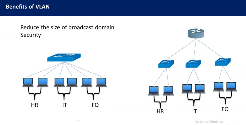
Advantages Performance –
The network traffic is full of broadcast and multicast. VLAN reduces the need to send such traffic to unnecessary destinations. e.g.-If the traffic is intended for 2 users but as 10 devices are present in the same broadcast domain, therefore, all will receive the traffic i.e. wastage of bandwidth but if we make VLANs, then the broadcast or multicast packet will go to the intended users only.
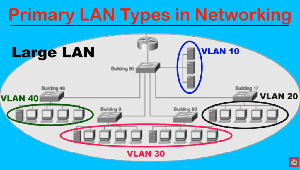
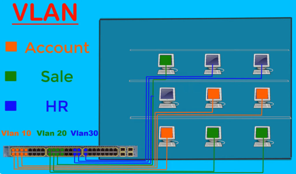
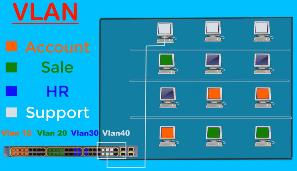
Formation of virtual groups –
As there are different departments in every organization namely sales, finance etc., VLANs can be very useful in order to group the devices logically according to their departments.
Security –
In the same network, sensitive data can be broadcast which can be accessed by the outsider but by creating VLAN, we can control broadcast domains, set up firewalls, restrict access. Also, VLANs can be used to inform the network manager of an intrusion. Hence, VLANs greatly enhance network security.
Flexibility –
VLAN provide flexibility to add, remove the number of host we want.
Cost reduction –
VLANs can be used to create broadcast domains which eliminate the need for expensive routers.By using Vlan, the number of small size broadcast domain can be increased which are easy to handle as compared to a bigger broadcast domain.
Disadvantages of VLAN
Complexity: VLANs can be complex to configure and manage, particularly in large or dynamic cloud computing environments.Limited
Scalability: VLANs are limited by the number of available VLAN IDs, which can be a constraint in larger cloud computing environments.
Limited security: VLANs do not provide complete security and can be compromised by malicious actors who are able to gain access to the network.
Limited interoperability: VLANs may not be fully compatible with all types of network devices and protocols, which can limit their usefulness in cloud computing environments.
Limited mobility: VLANs may not support the movement of devices or users between different network segments, which can limit their usefulness in mobile or remote cloud computing environments.
Cost: Implementing and maintaining VLANs can be costly, especially if specialized hardware or software is required.
Limited visibility: VLANs can make it more difficult to monitor and troubleshoot network issues, as traffic is isolated in different segments.
Real-Time Applications of VLAN
Virtual LANs (VLANs) are widely used in cloud computing environments to improve network performance and security. Here are a few
examples of real-time applications of VLANs:
Voice over IP (VoIP) : VLANs can be used to isolate voice traffic from data traffic, which improves the quality of VoIP calls and reduces the risk of network congestion.
Video Conferencing : VLANs can be used to prioritize video traffic and ensure that it receives the bandwidth and resources it needs for high-quality video conferencing.
Remote Access : VLANs can be used to provide secure remote access to cloud-based applications and resources, by isolating remote users from the rest of the network.
Cloud Backup and Recovery : VLANs can be used to isolate backup and recovery traffic, which reduces the risk of network congestion and improves the performance of backup and recovery operations.
Gaming : VLANs can be used to prioritize gaming traffic, which ensures that gamers receive the bandwidth and resources they need for a smooth gaming experience.
IoT : VLANs can be used to isolate Internet of Things (IoT) devices from the rest of the network, which improves security and reduces the risk of network congestion.
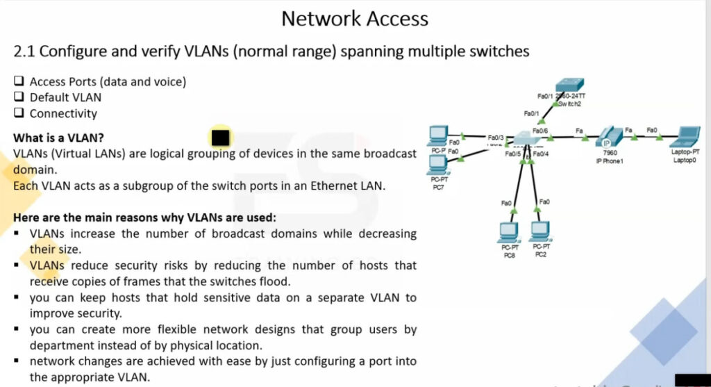
A VLAN (Virtual Local Area Network) is a logical subgroup within a physical network that is created to segment and isolate network traffic. It allows network administrators to group devices together based on functional or organizational requirements, regardless of their physical locations. VLANs enhance security, improve network performance, and simplify network management.
Instead of devices being part of the same broadcast domain based on physical connections (like being plugged into the same switch), VLANs logically segment the network, making it behave as though each VLAN is a separate network. This way, devices on different VLANs cannot communicate with each other without a router or layer 3 device.
VLANs can be categorized based on different criteria, such as their function in the network or how they are configured. Here are the main types of VLANs:
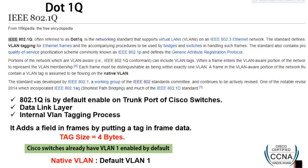
VLAN Tagging: Ethernet frames can be “tagged” with a VLAN identifier (VLAN ID) to indicate which VLAN the traffic belongs to. The most common standard for VLAN tagging is IEEE 802.1Q, which adds a 4-byte tag to the Ethernet frame header.
Trunking: Trunking allows multiple VLANs to be carried over a single physical link between two network devices. A trunk port is configured to pass multiple VLANs over the same link, while access ports are configured to belong to a single VLAN.
| VLAN Type | Purpose |
|---|---|
| Data VLAN | Used for regular user traffic, such as computers, printers, etc. |
| Voice VLAN | Used to segregate voice traffic, typically for VoIP devices. |
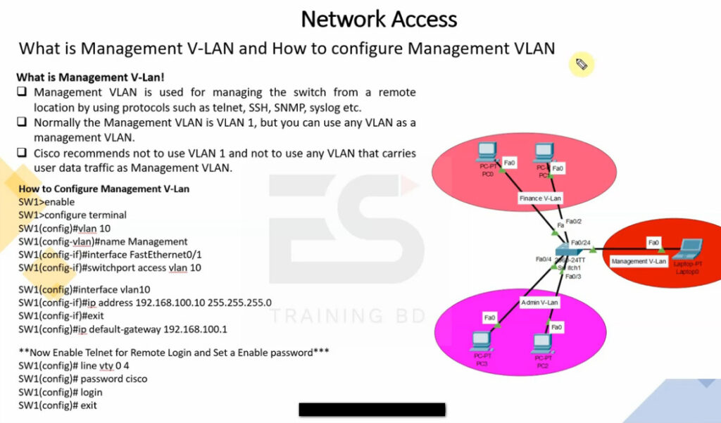
| Management VLAN | Dedicated for managing network devices like switches and routers. |
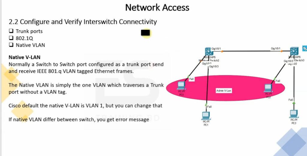
| Native VLAN | Default VLAN for untagged frames on a trunk link. |
| Private VLAN (PVLAN) | Provides additional isolation between devices within the same VLAN. |
| Default VLAN | The default VLAN (usually VLAN 1) that is used for all ports initially. |
| VLAN for Trunking | VLANs passed over a trunk link, allowing multiple VLANs on a single link. |
| Dynamic VLAN | VLANs dynamically assigned based on authentication or other criteria. |
| Excluded VLAN | VLANs deliberately blocked or excluded from certain ports for security reasons. |

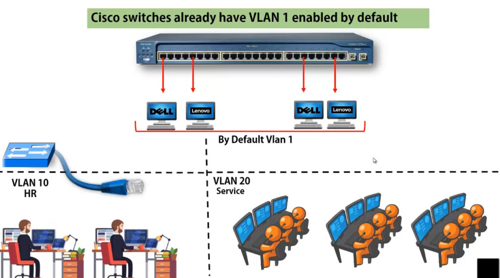

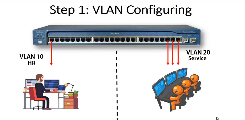
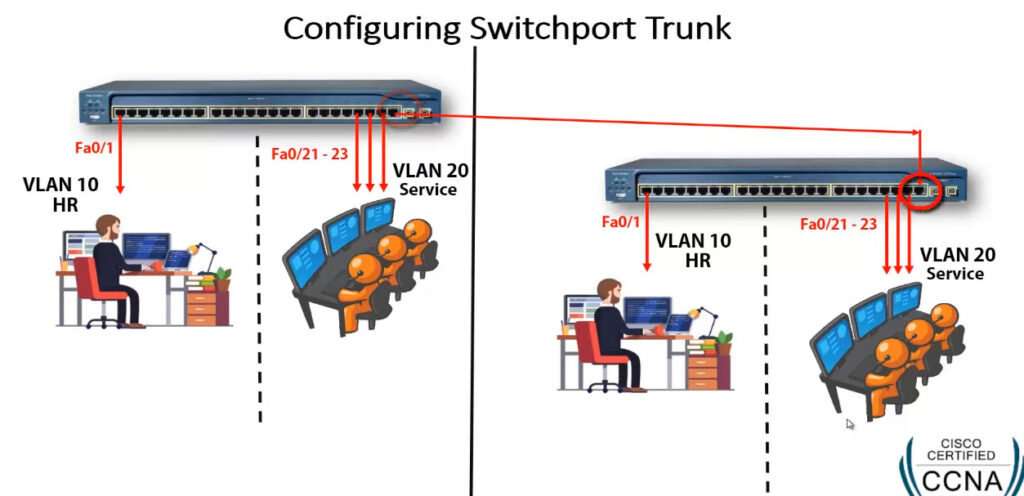
Switch VLAN Configuration
config t
vlan 10
name HR
exit
vlan 20
name SERVICES
exit
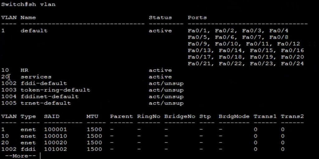
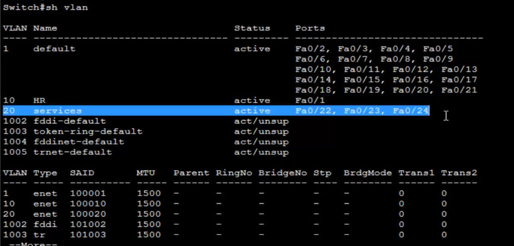
show vlan <This Commnd Checking All Created Vlan>
Assign Switch Port
config t
interface fa0/1
switchport mode acces
switchport acces vlan 10
exit
interface range fa0/22-24
switchport mode acces
switchport acces vlan 20
show vlan
show run <This Commnd View All Switch Configuration>
Configure Trunk For Cary Multiple VLAN Pass
interface fa0/24
switchport mode trunk
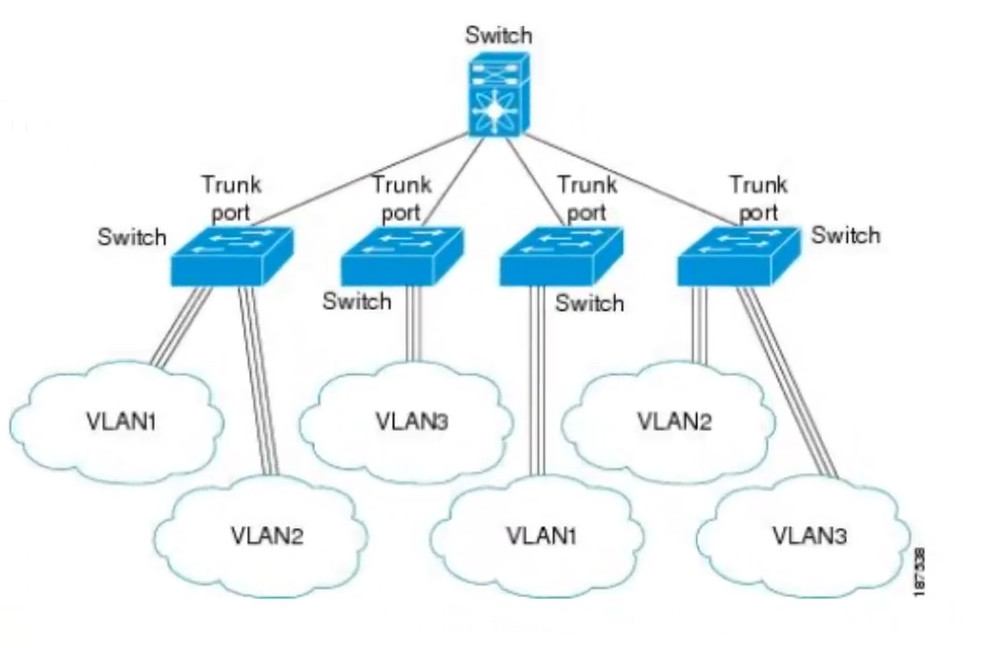
VLAN Trunking
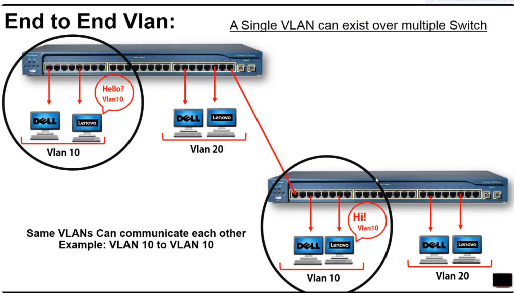
In order to overcome this scaling limitation, we can use another Ethernet technology called VLAN trunking. It creates only one link between the switches that support as many VLAN as needed. At the same time, it also keeps the VLAN traffic separate, so frames from VLAN 20 won’t go to devices in VLAN 10 and vice-versa. An example could be seen in figure 3. The link between switch 1 and switch 2 is a trunk link and you can see that both VLAN 10 and VLAN 20 pass through the link.
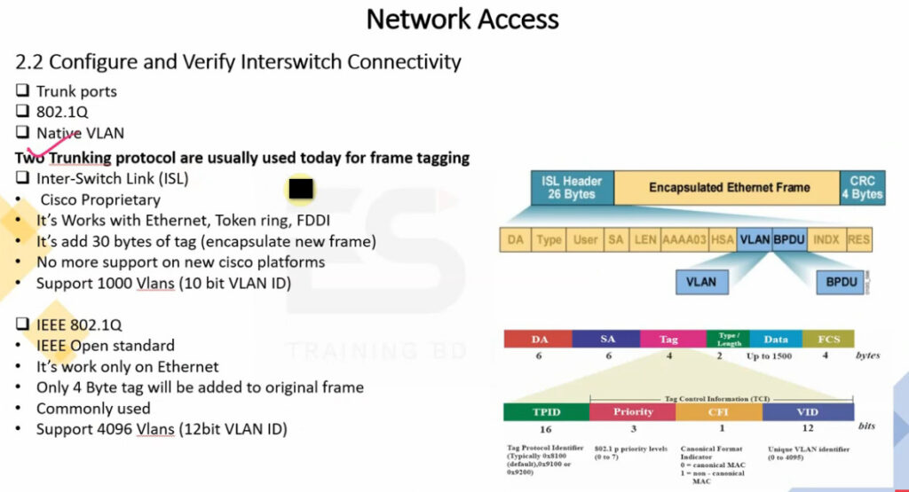
Two trunking protocols have been used on Cisco switches over the years – Inter-Switch Link (ISL) and IEEE 802.1Q. ISL was a Cisco proprietary tagging protocol predecessor of 802.1Q, it has been deprecated and is not used anymore. IEEE 802.1Q is the industry-standard trunking encapsulation at present and is typically the only one supported on modern switches.
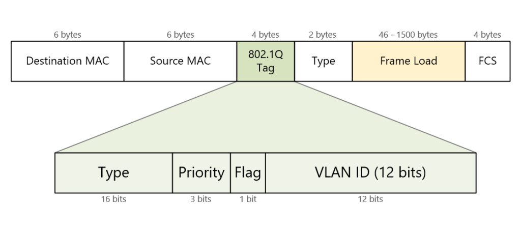
It is important to note that the tag adds 4 additional bytes to the Ethernet header of the frames. The most important field in the tag is the VLAN ID which is 12 bits long. It specifies the VLAN to which the frame belongs. Because values of 0x000 and 0xFFF are reserved, there are 4,094 possible VLAN numbers.
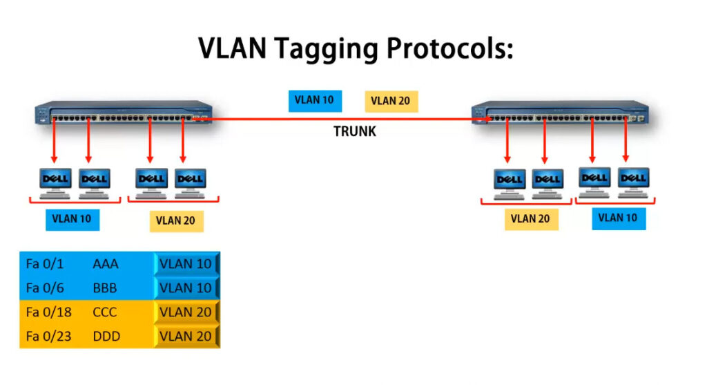
VLAN Tagging
VLAN trunking allows switches to forwards frames from different VLANs over a single link called trunk. This is done by adding an additional header information called tag to the Ethernet frame. The process of adding this small header is called VLAN tagging. If you look at Figure 4, end-station 1 is sending a broadcast frame. When switch 1 receives the frame, it knows that this is a broadcast frame and it has to send it out all its ports. However, switch 1 must tell switch 2 that this frame belongs to VLAN10. So before sending the frame to switch 2, SW1 adds a VLAN header to the original ethernet frame, with VLAN number 10 as shown in figure 4.
When switch 2 receives the frame, it sees that the frame belongs to VLAN 10, then it removes the header and forwards to the original ethernet frame to all its interfaces configured in VLAN10.
So in the given examples, when the ethernet frames are sent between the switches over the trunk link, they are tagged with VLAN header. When the receiving switch gets them, removes the VLAN tag and sends them to the clients in the VLAN, the frames are untagged.
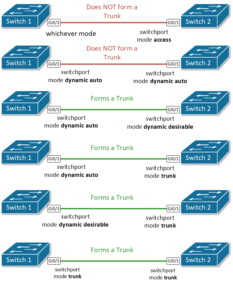
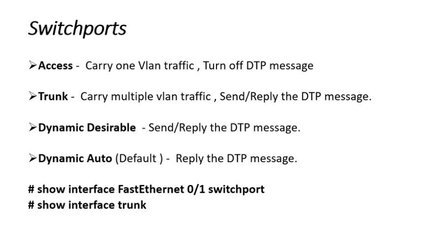
Switch interface modes
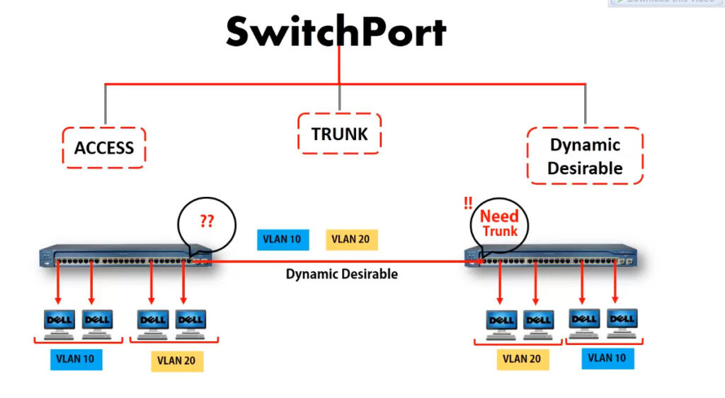
Each switch interface can operate as access or trunk port. Because in typical LAN deployment, there are hundreds or even thousands of switch ports, there is a protocol called Dynamic Trunking Protocol (DTP) that helps network administrators set the operational mode of interfaces automatically. By default, all Cisco switch ports are in operational state dynamic auto, which means that this Dynamic Trunking Protocol (DTP) is listening and trying to understand what is configured on the other side of the cable, and based on that to decide whether to become an access or trunk port. For example, if we have a link between SW1 and SW2, if we configure the interface on SW1 to be a trunk port, DTP will advertise this to the other side and the interface on SW2 will automatically set itelf in trunk mode and a trunk link will be formed between the switches.
| Mode | Behaviour |
|---|---|
| switchport mode dynamic auto | DEFAULT MODE for layer 2 interfaces of Cisco switches Passively waiting to convert the port into a trunk. (DTP listening for messages from the far side saying “let’s form a trunk”) Becomes a trunk if the other side of the link is configured with trunk or dynamic desirable mode |
| switchport mode dynamic desirable | Actively trying to convert the link to a trunk. (DTP actively sending messages to the far side saying “let’s form a trunk”) Becomes a trunk if the other side of the link is configured with trunk or dynamic desirable or dynamic auto. |
| switchport mode access | The interface becomes an access port. DTP negotiates the link as nontrunk link. |
| switchport mode trunk | The interface becomes a trunk port. DTP negotiates the link as trunk link. (DTP actively sending messages to the far side saying “let’s form a trunk”) |
| switchport mode nonegotiate | Disables the Dynamic Trunking Protocol (DTP). Interface mode is configured manually. |
Configuring Trunk ports
As we have already said, the default mode for Cisco switchports is dynamic auto. Therefore, in order to form a trunk, only one side of the link must be configured to actively negotiate it. Let’s configure Gi0/1 on SW1 to be actively trying to form a trunk and see what happens.
SW1#conf t
Enter configuration commands, one per line. End with CNTL/Z.

SW1(config)#interface GigabitEthernet 0/1
SW1(config-if)#switchport mode ?
access Set trunking mode to ACCESS unconditionally
dynamic Set trunking mode to dynamically negotiate access or trunk mode
trunk Set trunking mode to TRUNK unconditionally

SW1(config-if)#switchport mode dynamic ?
auto Set trunking mode dynamic negotiation parameter to AUTO
desirable Set trunking mode dynamic negotiation parameter to DESIRABLE

SW1(config-if)#switchport mode dynamic desirable
SW1(config-if)#end
%SYS-5-CONFIG_I: Configured from console by console

SW1#show interface trunk
Port Mode Encapsulation Status Native vlan
Gig0/1 desirable n-802.1q trunking 1

Port Vlans allowed on trunk
Gig0/1 1-1005

Port Vlans allowed and active in management domain
Gig0/1 1,10,20

Port Vlans in spanning tree forwarding state and not pruned
Gig0/1 1,10,20
You can see from the output of show interface trunk command that a trunk link formed, even though we haven’t configured anything on the other side of the link on switch 2. That is the function of the dynamic trunking protocol. Let’s check what is the status of the link according to switch 2.
SW2#sh interfaces trunk
Port Mode Encapsulation Status Native vlan
Gig0/1 auto n-802.1q trunking 1

Port Vlans allowed on trunk
Gig0/1 1-1005

Port Vlans allowed and active in management domain
Gig0/1 1,10,20

Port Vlans in spanning tree forwarding state and not pruned
Gig0/1 1,10,20