- 8777701917
- info@saikatinfotech.com
- Basirhat W.B

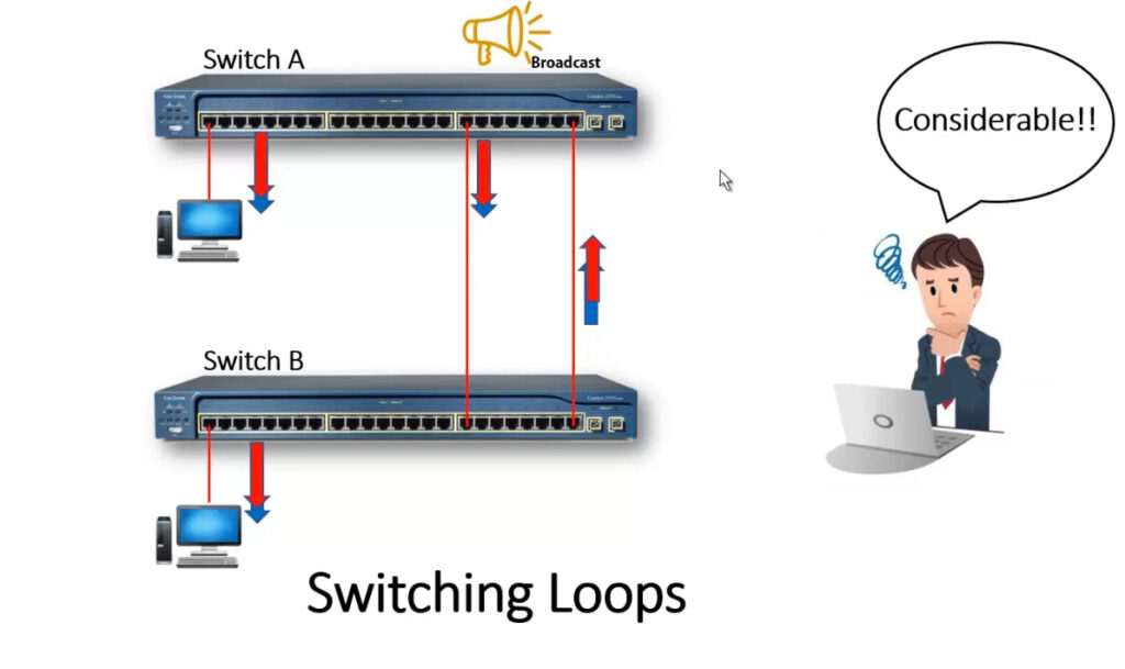
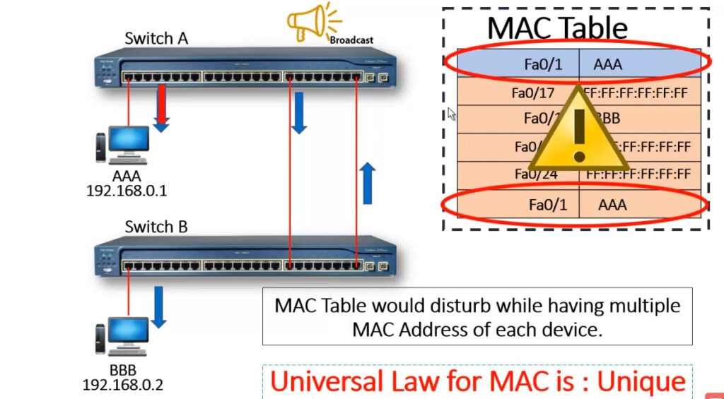
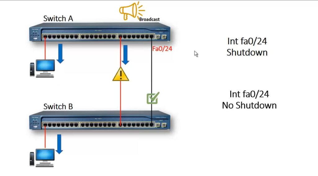
A Layer-2 switch belongs to only one broadcast domain, and will forward both broadcasts and multicasts out every port but the originating port. When a switching loop is introduced into the network, a destructive broadcast storm will develop within seconds. A storm occurs when broadcasts are endlessly forwarded through the loop. Eventually, the storm will choke off all other network traffic.
Spanning Tree Protocol (STP) was developed to prevent the broadcast storms caused by switching loops. STP was originally defined in IEEE 802.1D.
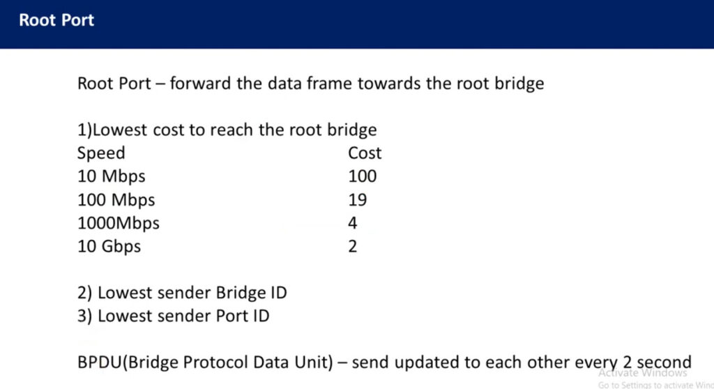
STP switches exchange Bridge Protocol Data Units (BPDU’s) to build the topology database. BPDU’s are forwarded out all ports every two seconds, to a dedicated MAC multicast address of 0180.c200.0000.
Building the STP topology is a multistep convergence process:
Once the full topology is determined, and loops are eliminated, the switches are considered converged. STP is enabled by default on all Cisco switches, for all VLANs.
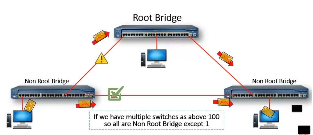
Electing an STP Root Bridge :
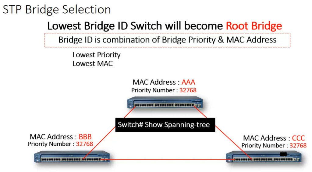
The first step in the STP convergence process is electing a Root Bridge, which is the central reference point for the STP topology. As a best practice, the Root Bridge should be the most centralized switch in the STP topology.
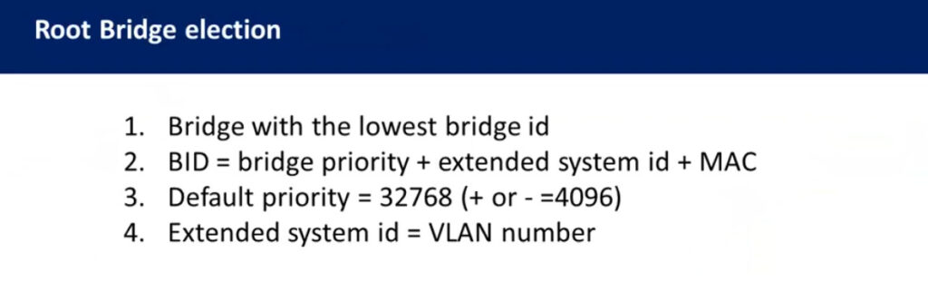
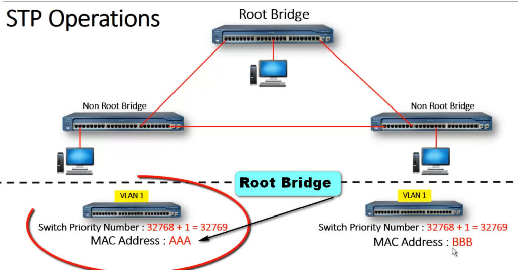
A Root Bridge is elected based on its Bridge ID, comprised of two components in the original 802.1D standard:
16-bit Bridge priority
48-bit MAC address
The default priority is 32,768, and the lowest priority wins. If there is a tie in priority, the lowest MAC address is used as the tie-breaker.
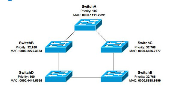
Switches exchange BPDU’s to perform the election process, and the lowest Bridge ID determines the Root Bridge:
SwitchB, SwitchC, and SwitchE have the default priority of 32,768.
SwitchA and SwitchD are tied with a lower priority of 100.
SwitchA has the lowest MAC address, and will be elected the Root Bridge.
By default, a switch will always believe it is the Root Bridge, until it receives a BPDU from a switch with a lower Bridge ID. This is referred to as a superior BPDU. The election process is continuous – if a new switch with the lowest Bridge ID is added to the topology, it will be elected as the Root Bridge.
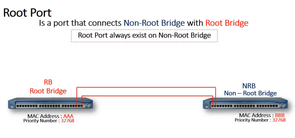
Identifying Root Ports :
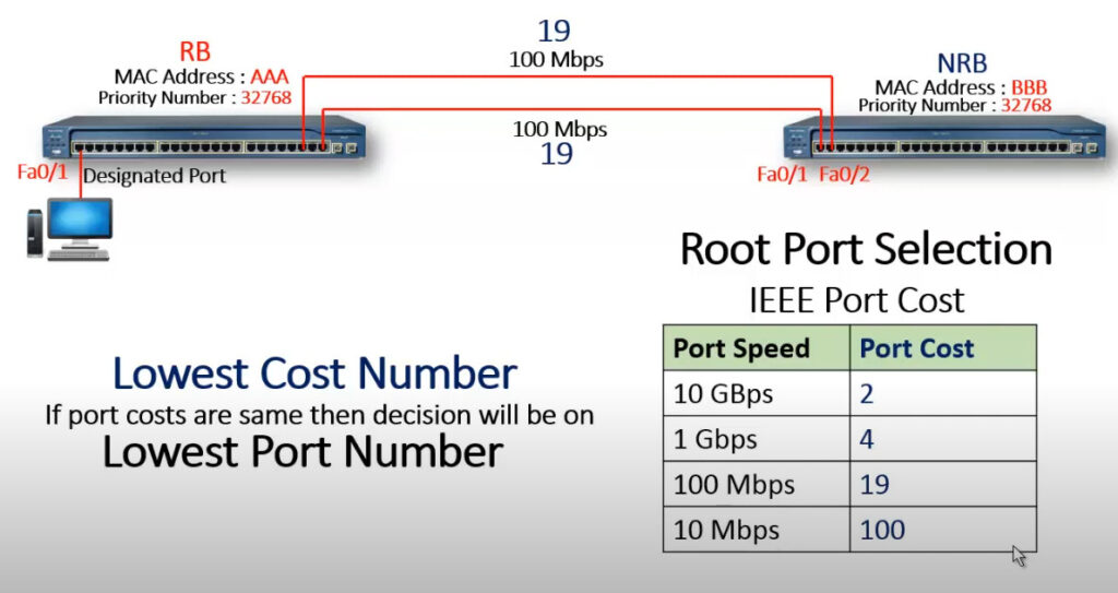
The root port of each switch has the lowest root path cost to get to the Root Bridge. Each switch can only have one root port. The Root Bridge cannot have a root port, as the purpose of a root port is to point to the Root Bridge. Path cost is a cumulative cost to the Root Bridge, based on the bandwidth of the links. The higher the bandwidth, the lower the path cost:
A lower cost is preferred. Consider the following example:
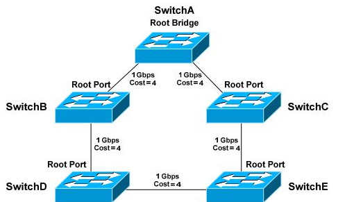
Each 1Gbps link has a path cost of 4. SwitchA has a cumulative path cost of 0, because it is the Root Bridge. Thus, when SwitchA sends out BPDU’s, it advertises a root path cost of 0.
SwitchB has two paths to the Root Bridge: • A direct connection to SwitchA, with a path cost of 4. • Another path through SwitchD, with a path cost of 16.
The lowest cumulative path cost is considered superior, thus the port directly connecting to SwitchA will become the root port. A BPDU advertising a higher path cost is often referred to as an inferior BPDU.
SwitchD also has two paths to the Root Bridge :
A path through SwitchB, with a path cost of 8. • A path through SwitchE, with a path cost of 12. • The port to SwitchB is preferred, and will become the root port.
Path cost can be artificially adjusted on a per-port basis:
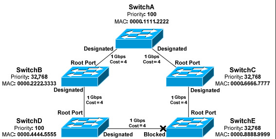
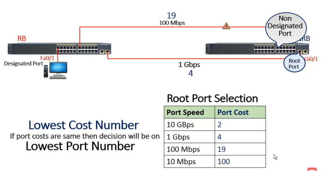
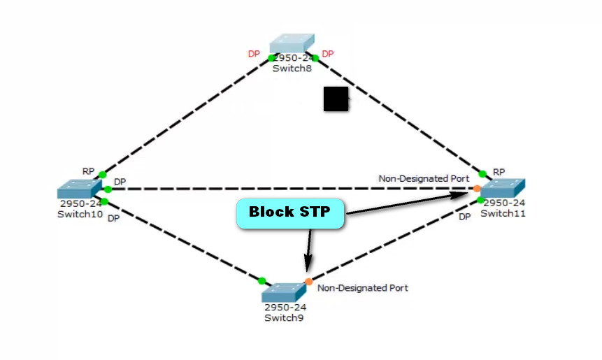
Identifying Designated Ports :
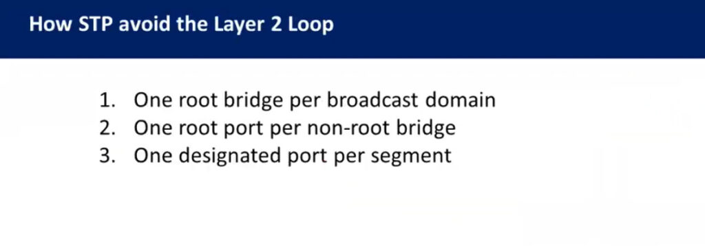
A single designated port is identified for each network segment. This port is responsible for forwarding BPDUs and frames to that segment.
Ports on the Root Bridge are never placed in a blocking state. Thus, the two ports off of SwitchA will automatically become designated ports.
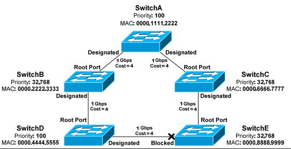
Remember, every network segment must have one designated port, regardless if a root port already exists on that segment
Normally, whichever switch has the lowest cumulative path cost will have its port become designated. The switch with the highest path cost will have its port blocked.
The lowest Bridge ID is used as the tiebreaker. SwitchD has a priority of 100, and SwitchE has the default priority of 32,768. Thus, the port on SwitchD will become the designated port. The port on SwitchE will be placed in a blocking state. As with electing the Root Bridge, if there is a tie in priority, the lowest MAC address is used as the tie breaker. Remember: Any port not elected as a root or designated port will be placed in a blocking state.
Port ID :
When electing root and designated ports, it is possible to have a tie in both path cost and Bridge ID. Consider the following example:
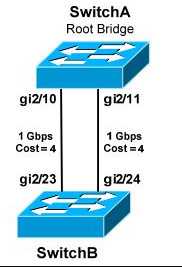
Port ID is used as the final tiebreaker, and consists of two components:
By default, the port priority of an interface is 128, and a lower priority is preferred. If there is a tie in priority, the lowest port number is preferred.
Remember: Port ID is the last tiebreaker STP will consider. STP determines root and designated ports using the following criteria, in order:
Lowest Bridge ID is always used to determine the Root Bridge.
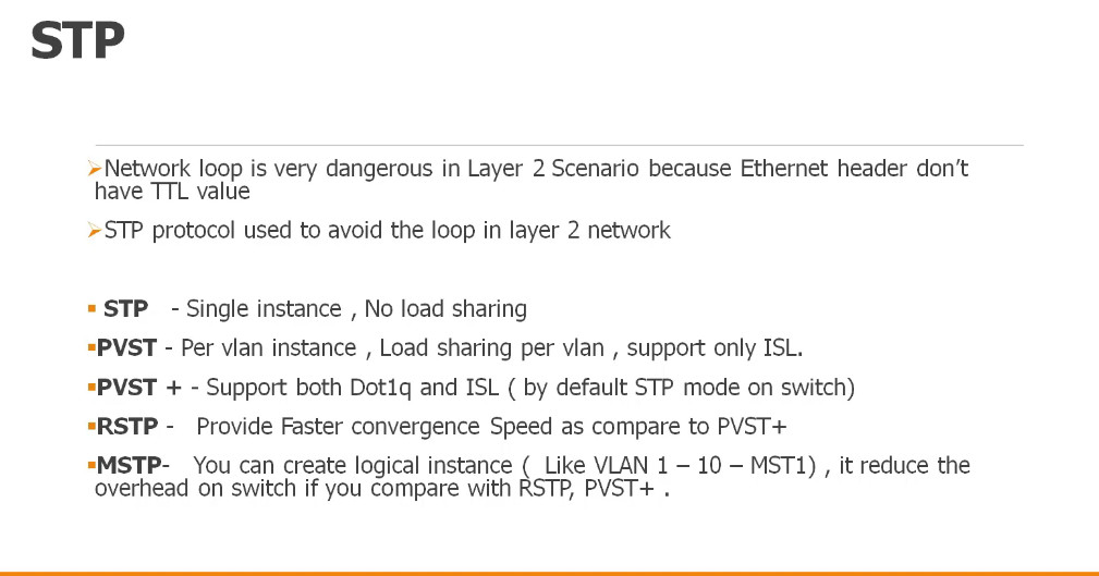
Versions of STP :
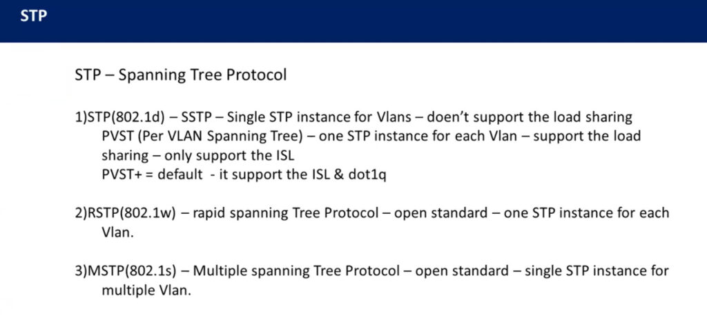
There are three flavors of the original 802.1D version of STP:
CST utilizes a single STP instance for all VLANs, and is sometimes referred to as mono spanning tree. All CST BPDU’s are sent over the native VLAN on a trunk port, and thus are untagged.
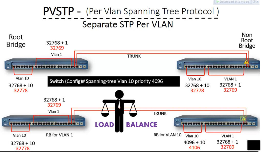
PVST employs a separate STP instance for each VLAN, improving flexibility and performance. PVST requires trunk ports to use ISL encapsulation. PVST and CST are not compatible.
The enhanced PVST+ is compatible with both CST and PVST, and supports both ISL and 802.1Q encapsulation. PVST+ is the default mode on many Cisco platforms.
Extended System IDs :
In the original 802.1D standard, the 64-bit Bridge ID consisted of two components:
IEEE 802.1t altered the Bridge ID to include an extended system ID, which identifies the VLAN number of the STP instance. The Bridge ID remained 64 bits, but now consisted of three components:
By stealing 12 bits from the bridge priority, the range of priorities is altered:
Note : Extended system ID’s are enabled by default and cannot be disabled if a switch platform does not support 1024 system MAC addresses.
Basic STP Configuration :
STP is enabled by default on all Cisco switches, for all VLANs and ports. PVST+ is the default STP mode on most modern Cisco platforms, allowing each VLAN to run a separate STP instance. STP can be disabled. This should be done with caution – any switching loop will result in a broadcast storm.
To disable STP for an entire VLAN: Switch(config)# no spanning-tree vlan 101
A range of VLANs can be specified: Switch(config)# no spanning-tree vlan 1 – 4094
STP can also be disabled on a per-port basis, for a specific
VLAN: Switch(config)# interface gi2/23 Switch(config-if)# no spanning-tree vlan 101
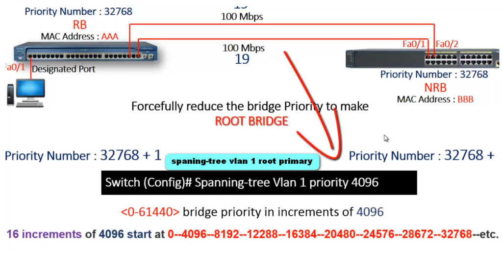
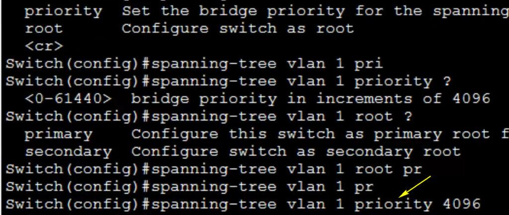
The switch with the lowest Bridge ID is elected as the Root Bridge. The priority can be adjusted from its default of 32,768, to increase the likelihood that a switch is elected as the Root Bridge. Priority can be configured on a per-VLAN basis. Remember that the priority must be in multiples of 4,096 when extended system IDs are enabled:
SwitchA(config)# spanning-tree vlan 101 priority 8192
A switch can be indirectly forced to become the Root Bridge for a specific
VLAN: SwitchA(config)# spanning-tree vlan 101 root primary
The root primary parameter automatically lowers the priority to 24,576. If another switch has a priority lower than 24,576, the priority will be lowered to 4,096 less than the current Root Bridge. STP does not technically support a backup Root Bridge. However, the root secondary command can increase the likelihood that a specified switch will succeed as the new Root Bridge in the event of a failure:
SwitchB(config)# spanning-tree vlan 101 root secondary
The root secondary parameter in the above command automatically lowers the switch’s priority to 28,672.
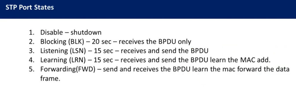
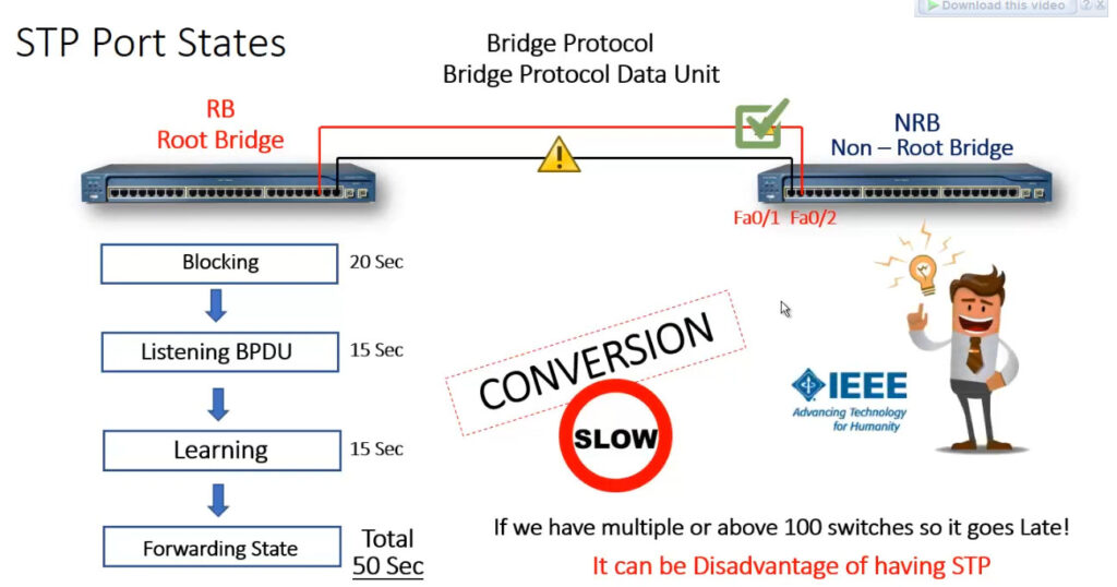
STP Port States:
As STP converges the switching topology, a switch port will progress through a series of states:
Initially, a switch port will start in a blocking state:
A port will then transition from a blocking to a listening state:
If a listening port is elected as a root or designated port, it will transition to a learning state: • A port must wait a brief period of time, referred to as the forward delay, before transitioning from a listening to learning state.
Finally, a learning port will transition to a forwarding state:
Technically, there is a fifth port state – disabled. A port in a disabled state has been administratively shutdown. A disabled port does not forward frames or participate in STP convergence.
Why does a port start in a blocking state? STP must initially assume that a loop exists. A broadcast storm can form in seconds, and requires physical intervention to stop.
Thus, STP will always take a proactive approach. Starting in a blocking state allows STP to complete its convergence process before any traffic is forwarded. In perfect STP operation, a broadcast storm should never occur.
To view the current state of a port: SwitchA# show spanning-tree interface gi2/10
STP Timers :
Switches running STP exchange BPDUs to build and converge the topology database. There are three timers that are crucial to the STP process:
The hello timer determines how often switches send BPDUs. By default, BPDUs are sent every 2 seconds.
Forward delay timer :
The forward delay timer determines how long a port must spend in both a learning and listening state:
Max age timer
The max age timer indicates how long a switch will retain BPDU information from a neighbor switch, before discarding it:
Timer values can be adjusted. However, this is rarely necessary, and can negatively impact STP performance and reliability.
Timers must be changed on the Root Bridge. The Root Bridge will propagate the new timer values to all switches using BPDUs. Non-root switches will ignore their locally configured timer values.
STP Diameter :
The default values of each STP timer are based on the diameter of the switching topology. The diameter is the length of the topology, measured in the number of switches including the Root Bridge.
By default, STP assumes a switching diameter of 7. This is also the maximum diameter. Note: The switching topology can contain more than seven switches. However, each branch of the switching tree can only extend seven switches deep, with the Root Bridge always at the top of the branch.
The diameter should be configured on the Root Bridge:
SwitchA(config)# spanning-tree vlan 101 root primary diameter 5
The diameter command adjusts the hello, forward delay, and max age timers. This is the recommended way to adjust timers, as the timers are tuned specifically to the diameter of the switching network.
STP Topology Changes :
Switches exchange two types of BPDUs when building and converging the topology database:
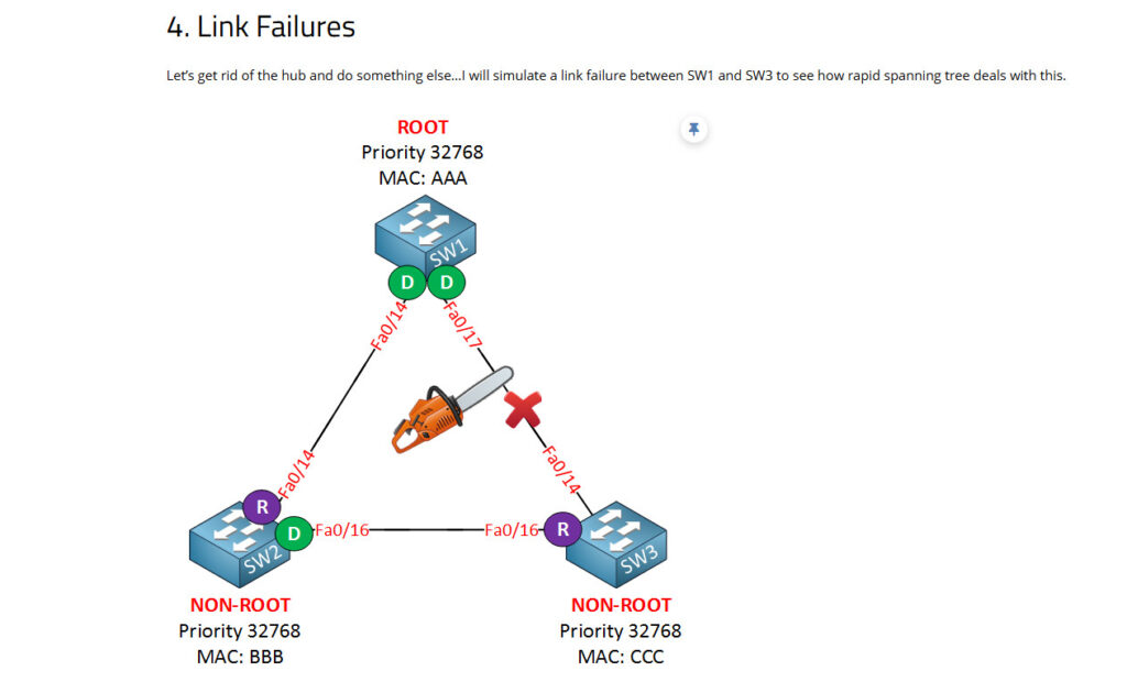
When a topology change occurs, a switch will send a TCN BPDU out its root port, destined for the Root Bridge. The TCN contains no information about the change – it only indicates that a change occurred
Consider the following example:
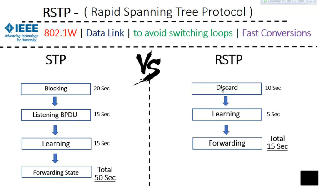
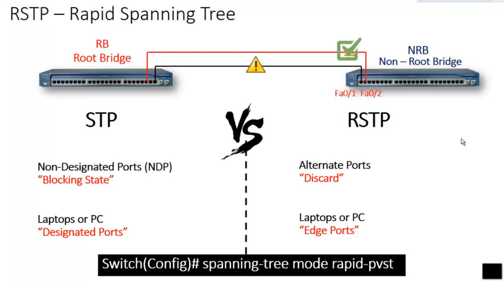
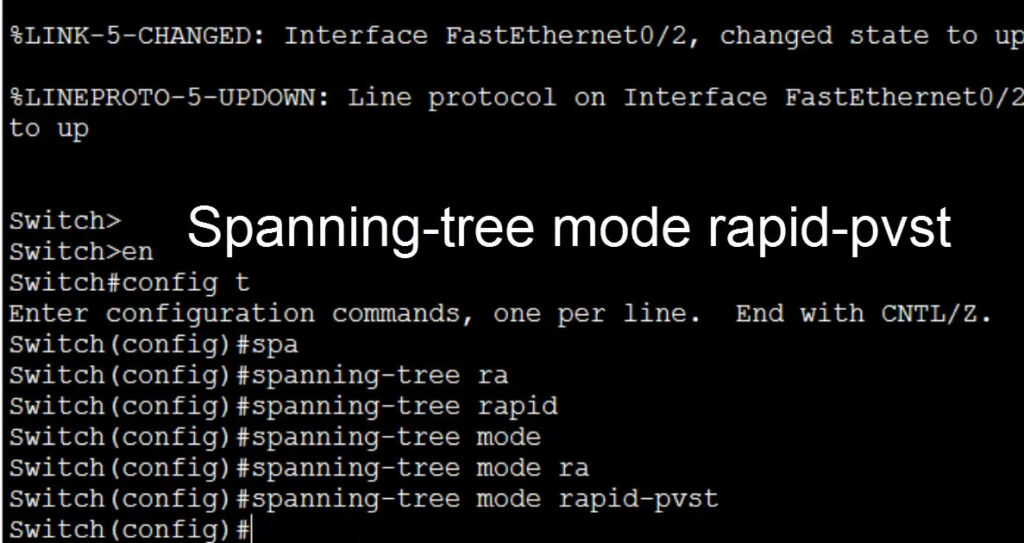
This is the topology I’m going to use. SW1 will be the root bridge in my example. First, we have to enable rapid spanning tree:
SW1(config)#spanning-tree mode rapid-pvstSW2(config)#spanning-tree mode rapid-pvstSW3(config)#spanning-tree mode rapid-pvstThat’s it…just one command will enable rapid spanning tree on our switches. The implementation of rapid spanning tree is rapid-pvst. We are calculating a rapid spanning tree for each VLAN.
Let’s continue. I’m going to enable this interface so that connectivity is fully restored:
SW1(config)#interface fa0/17
SW1(config-if)#no shutdown
Let’s look at an overview:
SW1#show spanning-tree
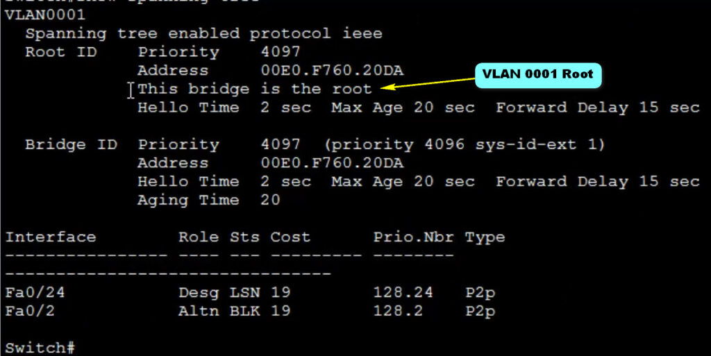
VLAN0001
Spanning tree enabled protocol rstp
Root ID Priority 4097
Address 0011.bb0b.3600
This bridge is the root
Hello Time 2 sec Max Age 20 sec Forward Delay 15 sec
Bridge ID Priority 4097 (priority 4096 sys-id-ext 1)
Address 0011.bb0b.3600
Hello Time 2 sec Max Age 20 sec Forward Delay 15 sec
Aging Time 300
Interface Role Sts Cost Prio.Nbr Type
------------------- ---- --- --------- -------- --------------------------------
Fa0/14 Desg FWD 19 128.16 P2p
Fa0/17 Desg FWD 19 128.19 P2pWe can verify that SW1 is the root bridge. This show command also reveals that we are running rapid spanning tree. Note that the link type is p2p. This is because my FastEthernet interfaces are in full duplex by default. Let’s run the same command on the other two switches:
SW2#show spanning-tree

VLAN0001
  Spanning tree enabled protocol rstp
  Root ID    Priority    4097
             Address     0011.bb0b.3600
             Cost        19
             Port        16 (FastEthernet0/14)
             Hello Time   2 sec  Max Age 20 sec  Forward Delay 15 sec

  Bridge ID  Priority    8193   (priority 8192 sys-id-ext 1)
             Address     0019.569d.5700
             Hello Time   2 sec  Max Age 20 sec  Forward Delay 15 sec
             Aging Time 300

Interface           Role Sts Cost      Prio.Nbr Type
------------------- ---- --- --------- -------- --------------------------------
Fa0/14              Root FWD 19        128.16   P2p
Fa0/16 Desg FWD 19 128.18 P2pSW3#show spanning-tree
VLAN0001
Spanning tree enabled protocol rstp
Root ID Priority 4097
Address 0011.bb0b.3600
Cost 19
Port 14 (FastEthernet0/14)
Hello Time 2 sec Max Age 20 sec Forward Delay 15 sec
Bridge ID Priority 32769 (priority 32768 sys-id-ext 1)
Address 000f.34ca.1000
Hello Time 2 sec Max Age 20 sec Forward Delay 15 sec
Aging Time 300
Interface Role Sts Cost Prio.Nbr Type
---------------- ---- --- --------- -------- --------------------------------
Fa0/14 Root FWD 19 128.14 P2p
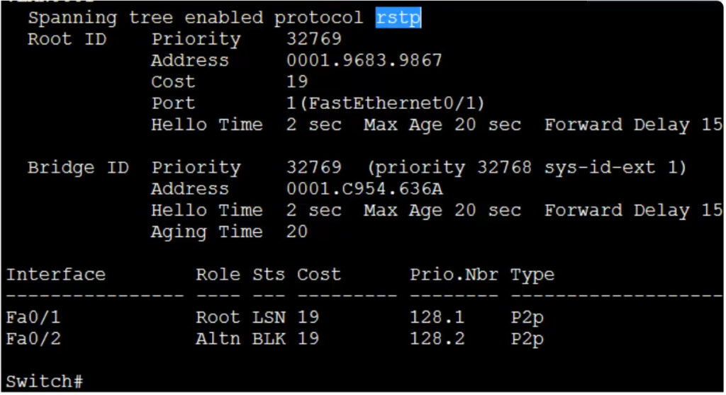
Fa0/16 Altn BLK 19 128.16 P2pHere are SW2 and SW3. Nothing new here. It’s the same information as classic spanning tree. Here’s what the topology looks like now:
Let’s add another link between SW2 and SW3 to see if this influences our topology:
SW2#show spanning-tree | begin Interface
Interface           Role Sts Cost      Prio.Nbr Type
------------------- ---- --- --------- -------- --------------------------------
Fa0/14              Root FWD 19        128.16   P2p
Fa0/16              Desg FWD 19        128.18   P2p
Fa0/17 Desg FWD 19 128.19 P2pSW3#show spanning-tree | begin Interface
Interface Role Sts Cost Prio.Nbr Type
---------------- ---- --- --------- -------- --------------------------------
Fa0/14 Root FWD 19 128.14 P2p
Fa0/16 Altn BLK 19 128.16 P2p
Fa0/17 Altn BLK 19 128.17 P2pNothing spectacular, we just have another designated port on SW2 and another alternate port on SW3. Let me add that alternate port to the topology:
So far, the topology with rapid spanning tree looks the same as with classic spanning tree. Now let me show you something you haven’t seen before. I will add a hub between SW2 and SW3:
Now take a look again at the interfaces:
SW2#show spanning-tree | begin Interface

Interface           Role Sts Cost      Prio.Nbr Type
------------------- ---- --- --------- -------- --------------------------------
Fa0/14               Root FWD 19        128.5    P2p
Fa0/16               Desg FWD 100       128.3    Shr
Fa0/17 Back BLK 100 128.4 Shr SW3#show spanning-tree | begin Interface
Interface Role Sts Cost Prio.Nbr Type
--------- -------- --------------------------------
Fa0/14 Root FWD 19 128.5 P2p
Fa0/16 Altn BLK 100 128.3 Shr
Fa0/17 Altn BLK 100 128.4 ShrHere’s something new. SW2 has a backup port. Because of the hub in the middle, SW2 and SW3 will hear their own BPDUs.
You can also see that the link type is shr (shared). That’s because the hub causes these switches to switch their interfaces to half duplex. Here’s the topology picture again:
You probably won’t ever see the backup port on a production network since hubs are scarce now, but if you see it, you’ll know why…
STP, PVST, and RSTP are different types of Spanning Tree Protocols used in computer networking to prevent loops in Ethernet networks and to ensure a loop-free topology.
Here’s a breakdown of each:
To summarize: