- 8777701917
- info@saikatinfotech.com
- Basirhat W.B

The problem with IPv4 addresses
An IP address is used as an endpoint identifier in IP-based communications. It is just like a telephone number. When you want to call another person over your mobile, you dial his telephone number. The call is established between phone numbers.
In the same way, when a device wants to communicate using IP communication, it sends the data to the remote end’s IP address. The communication is established between IP addresses. Every mobile phone has a telephone number. In the same way, every device needs an IP address to send and receive data over an IP network.
IPv4 addresses are limited number. A key point here is that, by standard, an IPv4 address is 32 bits long, meaning there are only 4,294,967,296 possible unique IP addresses (and they were officially exhausted in April 2017). That’s it; new addresses could never be produced. The IPv4 address space is a finite resource.
The original idea when the Internet protocol was first introduced was that every organization would ask for and be given an IP address range, and IP addresses would be unique and not reused. People thought we had so many IPv4 addresses (4 billion) that everybody would have a unique IP that nobody else uses anywhere on the planet.
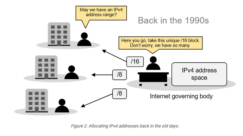
So, the Internet governing body was giving big, classful blocks of IP addresses (/8, /16, or /24) to every organization that asked for it. This model worked for a while. However, in the mid-1990s, it became extremely evident that the Internet was growing so fast that we would run out of addresses in a few years.
Then, people realized we needed a new IP protocol that supported more addresses, so IPv6 was introduced. This protocol uses 128-bit addresses instead of 32-bit, allowing for 2128 addresses. However, most organizations had already invested a lot of money in the adoption of IPv4. They were unwilling to reinvest time and money to migrate to IPv6, so they were looking for another solution.
The solution came through combining two network standards that worked together to save IPv4 address space: Private IPv4 addresses (RFC1918) and Network Address Translation (NAT).
The private IPv4 space (RFC1918)
If we combine the following two statements:
It is evident that, at some point, there will not be enough IPv4 addresses for every device on the planet. To overcome this problem, people came up with a brilliant idea:
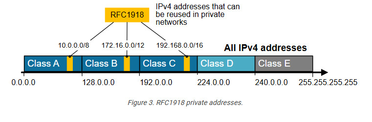
And that’s how the private IPv4 address space was born. A small portion of each class of usable IPv4 addresses was dedicated to addressing inside private networks (highlighted in yellow in the diagram below). These addresses were called private IP addresses and can be used anywhere by anyone without permission. They are not subject to IANA allocation.
IPv4 private addresses are not routable on the public Internet. These addresses are typically used within internal networks (e.g., home, office, or enterprise environments), and devices with private IP addresses can communicate within that network. However, they must pass through a device like a router performing Network Address Translation (NAT) to access the Internet.
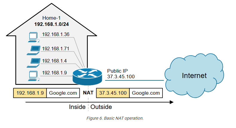
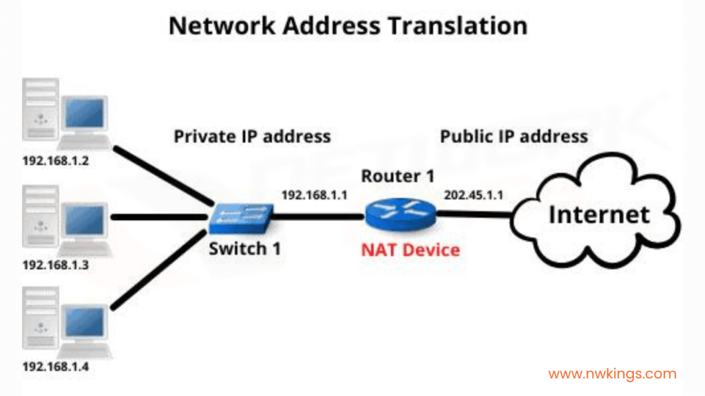
Every home network in the diagram below uses the same private network 192.168.1.0/24. For example, every device inside Home-1 has a private IPv4 address. However, when a device communicates with a host on the Internet, its address is translated into a public address assigned to the Internet router (37.3.45.100). All devices in Home-1 share this public IPv4 address when talking to the Internet.

The idea is that anyone can use these addresses or re-use them for as many hosts as they like on their internal network. NAT can then translate the multitude of hosts using Private addresses into a much smaller set of Public addresses – thereby curbing the rate at which IPv4 addresses are being utilized.
What is NAT?
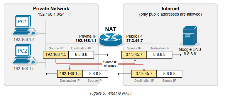
Network Address Translation (NAT) is a network capability that allows a device (typically a router or a firewall) to modify the IP address information in the IP packet headers while in transit. For example, let’s look at the diagram shown below. PC2 is configured with the private IPv4 address 192.168.1.5. This address is not routable on the Internet. However, PC2 can access the Internet because the router does Network Address Translation (NAT). When PC2’s packets reach the router, the router changes the source IP address in the IP header from 192.168.1.5 to 37.3.45.7, as shown in the diagram. Hence, all devices on the Internet see PC2’s traffic as coming from the public IP address 37.3.45.7.
NAT is most commonly used to enable multiple devices on a private network to access the internet using a single public IP address, which helps conserve the limited number of IPv4 addresses available. For example, all devices inside Home-1, as shown in the diagram below, use private IPv4 addresses from subnet 192.168.1.0/24. The router translates all internal IP addresses to the public IPv4 address assigned to the interface that connects to the Internet. Devices on the Internet see all traffic from Home-1 as coming from the public IP address 37.3.45.100.
You can see that NAT and private IPv4 addresses work together to conserve IPv4 address space by allowing many devices in a local network to share a single public IPv4 address. Without NAT and private IPv4 addresses, every device inside Home-1 would have required a unique public IP address. This would have depleted the available IPv4 addresses would long ago due to the rapid growth of devices connected to the internet.
Static NAT
A device, such as a router or firewall, can change the IP address information in the packets’ headers while packets pass through. This network function is called Network Address Translation (NAT) and is shown in the diagram below.
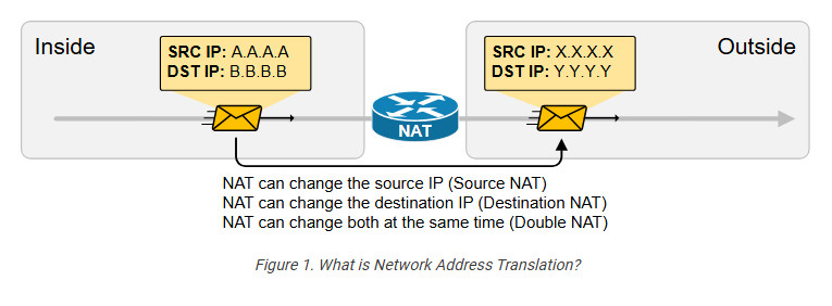
We have a packet with source IP “A.A.A.A” and destination IP “B.B.B.B” that goes through address translation. After the packet passes through the router, it has source IP “X.X.X.X” and destination IP “Y.Y.Y.Y.”
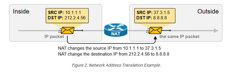
The following diagram shows an example of NAT with real IPv4 addresses. Notice something fundamental. Typically, organizations use NAT to translate private IPv4 addresses into public IPv4 addresses. However, from NAT’s perspective, it doesn’t matter whether the IPs are public or private. NAT can translate any IPv4 address to any other IPv4 address, whether private or public. In the example below, the NAT router translates the source IPv4 10.1.1.1 to 37.3.1.5 (private to public) and the destination IPv4 address 212.2.4.56 to 8.8.8.8 (public to public).
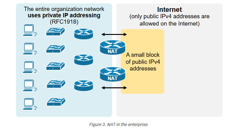
NAT is so ubiquitous and well-accepted that organizations primarily use private IPv4 addresses inside the entire network. Then, they use a small number of public IPv4 addresses on the internet-facing devices and use NAT to translate between the two, as shown in the diagram below.
an change a packet’s source, destination, or both source and destination IP addresses while it passes through a router or a firewall. In 99% of implementations, NAT changes only the packet’s source address, which is typically private, with a public IPv4 address. This process is referred to as source NAT because only the source IP address is being changed (the destination IP address in the packet is left untouched).
Static Source NAT
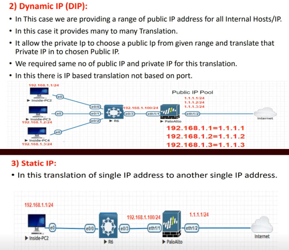
Static NAT is the most straightforward type of network address translation. An IPv4 address on the inside is always mapped to the same IPv4 address on the outside via a configuration command. For example, the IP address 10.1.1.1 is always replaced with 37.3.1.1 when a packet goes through the NAT router, as shown in the diagram below.

This static NAT rule allows PC1 to access the Internet because Internet hosts see PC1’s traffic as coming from public IP address 37.3.1.1. However, if a second PC must access the Internet, we need a second public IPv4 address and a second static NAT rule.
For example, if we have three PCs, as shown in the diagram below, we need three public IPv4 addresses and three static NAT rules. However, notice that the public IPv4 subnet assigned on the outside interface of the router is /26, which means we can only have 64 addresses. If we have 100 hosts on the inside, we cannot configure a static one-to-one mapping for all of them because we only have 64 public IPv4 addresses on the router’s outside interface.
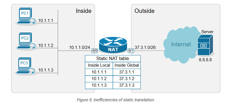
This example outlines the following essential aspects of Static NAT.
You may be wondering why this network translation technique even exists if it doesn’t conserve IP addresses. The truth is that static NAT is typically not an organization’s primary network translation technique. For most hosts with private IPv4 addresses, the organization most likely uses Dynamic NAT with Overload (more on it in the following lessons). Static NAT is typically used only for some particular IP addresses assigned to special hosts. Here are some reasons why:
With static NAT, a specific internal private IP is always mapped to a specific public IP, making the translation predictable. This is useful for services that need to be consistently reachable from the outside, such as Web servers, Mail servers, and VPN gateways. For example, we have a web server inside the organization that has a private IPv4 address, 10.1.1.3, as shown in the diagram below.
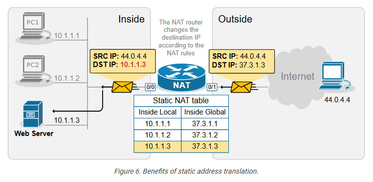
The NAT router has a static one-to-one mapping between 10.1.1.3 and 37.3.1.3. This allows hosts on the outside to send traffic to 37.3.1.3, and the static NAT rule ensures that incoming traffic is always forwarded to the internal web server 10.1.1.3, as shown in the diagram above.
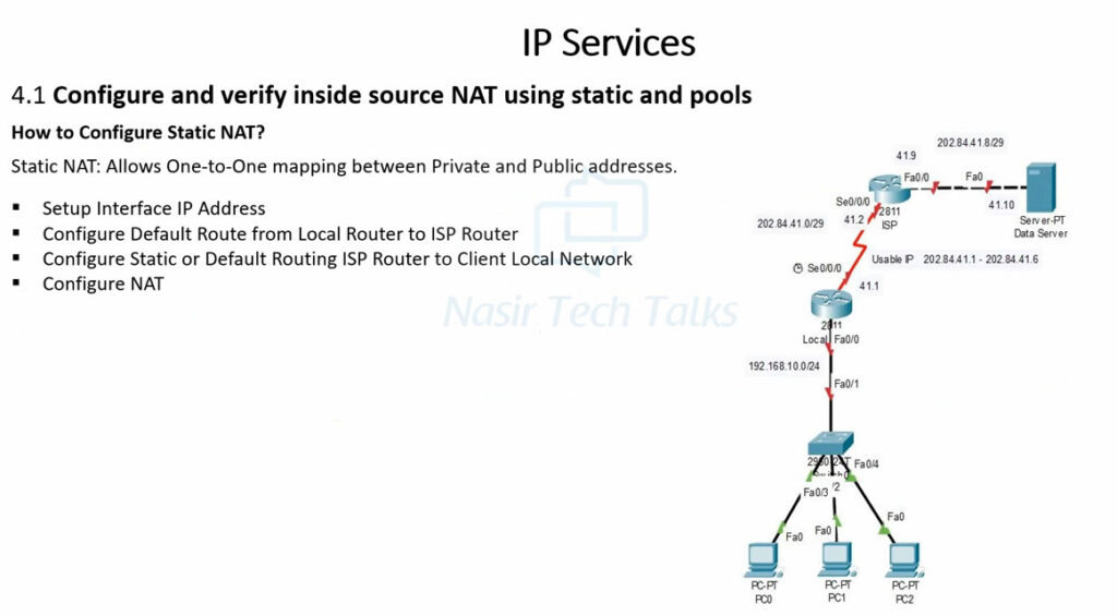
Configuring Static NAT
Let’s now see how to configure a router to perform static source network address translation. We will use a very basic topology, which you can download from the section at the end of the lesson and practice yourself.
The configuration process can be broken down into two main steps that are independent of one another:
Step 1. Defining Inside and Outside from the point of view of the local router.
Step 2. Configuring the NAT rules.
Step 1. Defining Inside and Outside
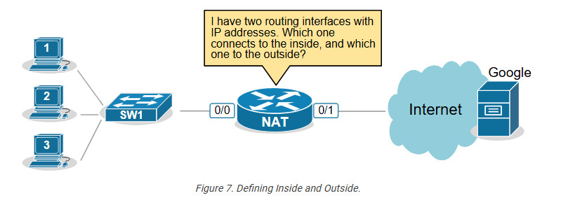
The first step in configuring network address translation is the same for every type of NAT – the router must identify which interfaces connect to the Inside which to the Outside.
A router cannot independently determine which interfaces connect to the organization’s network and which connect to an external network such as the Internet. For the router, every interface is the same—a layer 3 port with an IP address.
That’s why we must explicitly define the NAT zones on the router as follows:
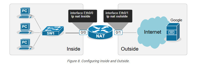
For example, we explicitly tell the router shown in the diagram above that its interface Ethernet0/0 connects to the Inside and Eth0/1 connects to the Outside by applying the configuration shown in the output below.
interface range Ethernet0/0
ip address 10.1.1.254 255.255.255.0
ip nat inside
!
interface Ethernet0/1
ip address 37.3.1.254 255.255.255.0
ip nat outside
!
Notice that a router may have multiple interfaces connecting to the Inside and multiple interfaces connecting to the Outside.
Step 2. Configuring NAT rules.
The second step in the configuration process is to define the network address translation rules. The following diagram shows the rules we need to configure.
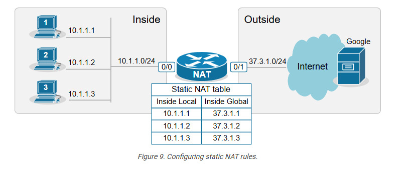
We apply one configuration command in global configuration mode for every one-to-one mapping, as shown in the output below.
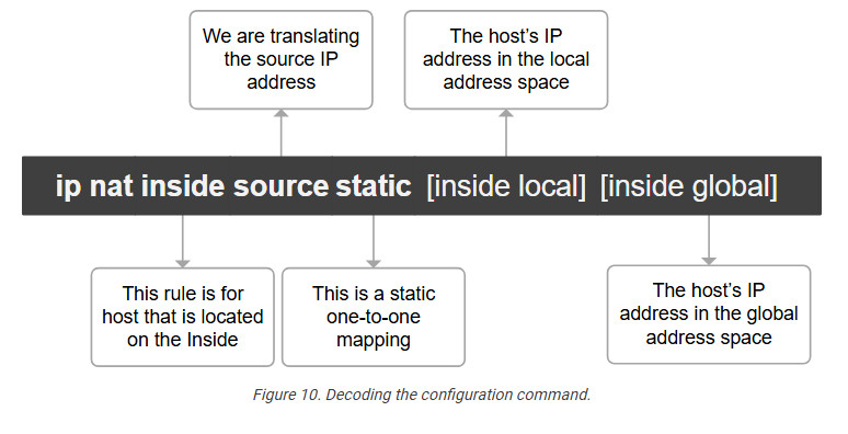
ip nat inside source static 10.1.1.1 37.3.1.1
ip nat inside source static 10.1.1.2 37.3.1.2
ip nat inside source static 10.1.1.3 37.3.1.3
Let’s decode the IP nat command that we use.
We have configured static network address translation for each local host in the topology. Now, let’s verify that the hosts can reach the Google server.
Verifying the network address translation
We use the following command to verify that the network address translation is working. Notice the terms “Inside local,” “Inside global,” “Outside local,” and “Outside global.”
NAT# sh ip nat translations

Pro Inside global Inside local Outside local Outside global
icmp 37.3.1.1:3 10.1.1.1:3 8.8.8.8:3 8.8.8.8:3
--- 37.3.1.1 10.1.1.1 ---
It is essential to understand what each of those terms means, so let’s zoom in.
Decoding the NAT table
One of the most important goals of this lesson is to ensure you understand the four main NAT table terms:
Let’s use the diagram below to introduce the key terms. Notice that we have a static one-to-one mapping that allows the host 10.1.1.1 on the inside to reach the host 8.8.8.8 on the Internet.
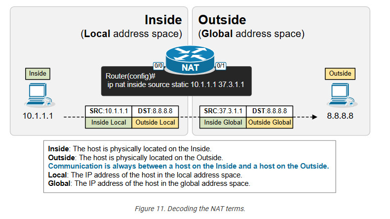
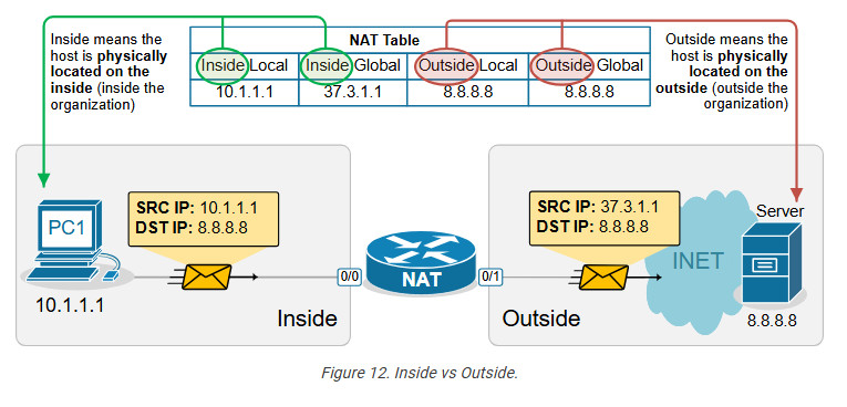
First, remember that from the perspective of the NAT router, every communication is between a host on the Inside and a host on the Outside. (Having in mind that Inside and Outside are already defined using the ip nat inside/outside command). One host is referenced as Inside and the other as Outside, as shown in the diagram below.
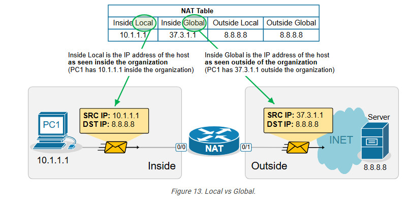
The following diagram visualizes the difference between the Local and Global terms.
Static address translation can be configured in the opposite direction for the host on the outside. The Outside host with Outside Global address 8.8.8.8 can be represented with an Outside Local address 10.1.1.8 on the inside, depending on the network requirements.
Another useful NAT verification tool is the show ip nat statistics command. It clearly shows the inside and outside interfaces and the type of NAT rules that are configured.
NAT# sh ip nat statistics
Total active translations: 3 (3 static, 0 dynamic; 0 extended)
Outside interfaces:
Ethernet0/1
Inside interfaces:
Ethernet0/0
Hits: 9 Misses: 0
CEF Translated packets: 9, CEF Punted packets: 0
Reserved port setting disabled provisioned no
Expired translations: 1
Dynamic mappings:
nat-limit statistics:
max entry: max allowed 0, used 0, missed 0
Key takeaways
Dynamic NAT
This lesson continues our discussion on Network Address Translation by examining Dynamic NAT. At the end of the lesson, you can download the EVE-NG virtual machine and practice the configurations on your own.
What is Dynamic NAT?
Dynamic NAT is basically a static one-to-one mapping between an inside local and inside global that happens automatically. We have seen in the previous lesson that with Static NAT, a network administrator manually configures every one-to-one mapping on the router. For example, to map the inside local address 10.1.1.1 to inside global 37.3.1.1, a network admin must configure the following configuration line on the router:
Router(config)# ip nat inside source static 10.1.1.1 37.3.1.1Suppose there are many inside local and inside global addresses. In that case, the network admin must configure many configuration lines on the router and statically pair each inside local and global addresses.
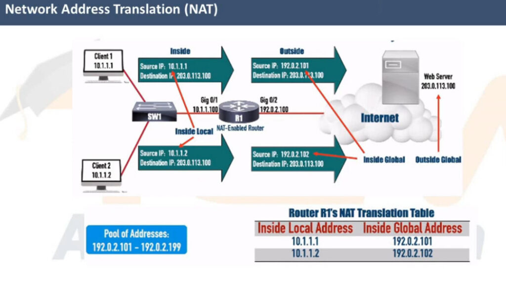
Dynamic NAT is a method of dynamically mapping inside local addresses (typically private ones) to inside global IP addresses (typically public ones) from a predefined pool of global IPs. Unlike Static NAT, where there’s a fixed one-to-one mapping between local and global addresses, Dynamic NAT maps local to global addresses on a first-come, first-served basis.
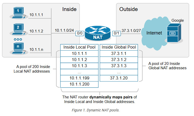
Let’s see how Dynamic NAT works in a few steps, as visualized in the diagram below:
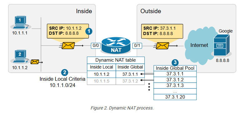
When step 3 is complete, the router adds a dynamic entry in its NAT table for the pair (10.1.1.2, 37.3.1.1) and keeps the entry until traffic flows between the PC2 and the host on the Internet. As long as the entry exists in the table, only host 10.1.1.2 can use the public address 37.3.1.1. The default timeout for the dynamic entry is 24 hours. IIf no traffic is seen in 24 hours, the entry is deleted from the table, and the public IP address is returned to the NAT pool.
Suppose another host, PC5 (10.1.1.5), sends packets destined for the Internet at the same time. The NAT router performs the same steps and dynamically maps the PC5’s private address, 10.1.1.5, to the next available public address from the pool – 37.3.1.2, as shown in the diagram above. The router keeps mapping Inside Local addresses to the next available Inside Global address until all addresses in the NAT pool are allocated. Then, if a packet arrives and there are no available public IPv4 addresses in the pool, the router discards the incoming packet. The size of the pool defines the maximum number of inside hosts that can access the Internet at the same time.
Notice the following key aspects of Dynamic NAT:
Now let’s move on to the configuration portion of the lesson.
Configuring Dynamic NAT
For this example, we are going to use the topology shown in the diagram below. There are three hosts inside the organization, which must be able to access the Google server and the Internet. The organization has purchased the following public IPv4 address from the ISP: 37.3.1.1 – 37.3.1.20.

Configuring any network address translation starts with identifying the Inside and Outside interfaces of the router. In this example, we configure the Eth0/0 interface as Inside and the Eth0/1 interface as outside, as shown in the output below.
interface Ethernet0/0
ip address 10.1.1.254 255.255.255.0
ip nat inside
!
interface Ethernet0/1
ip address 37.3.1.30 255.255.255.224
ip nat outside
!
The next step is configuring an access list defining the Inside Local criteria. Basically, when a packet enters the router on the NAT-inside interface, the router will check whether the source IP address is from the configured subnet. In our example, we will translate the source addresses from subnet 10.1.1.0/24 so the ACL looks like this:
ip access-list standard INSIDE_LOCAL
10 permit 10.1.1.0 0.0.0.255
!
Then, we need to define the pool of Inside Global addresses. In our case, we are given the range of addresses 37.3.1.1-37.3.1.20, so we configure the pool as follows:
ip nat pool INSIDE_GLOBAL 37.3.1.1 37.3.1.20 prefix-length 27
Lastly, we configure the NAT rule. Notice that the command references the access list and the pool that we have just configured.
ip nat inside source list INSIDE_LOCAL pool INSIDE_GLOBAL
The command basically tells the router – “When a packet arrives on your inside interface, and the packet’s source address matches the Inside Local criteria (10.1.1.0/24), map it to the next available public IPv4 address from the Inside Global pool.”
Verifying Dynamic NAT
Immediately after the router has been configured, its NAT table is empty. We must first initiate some traffic from Inside to Outside in order to trigger the dynamic translation. Let’s ping from the hosts to the Google server.
PC1> ping 8.8.8.8
Type escape sequence to abort.
Sending 5, 100-byte ICMP Echos to 8.8.8.8, timeout is 2 seconds:
.!!!!
Success rate is 80 percent (4/5), round-trip min/avg/max = 1/2/6 ms
PC2> ping 8.8.8.8
Type escape sequence to abort.
Sending 5, 100-byte ICMP Echos to 8.8.8.8, timeout is 2 seconds:
.!!!!
Success rate is 80 percent (4/5), round-trip min/avg/max = 1/4/7 ms
PC3> ping 8.8.8.8
Type escape sequence to abort.
Sending 5, 100-byte ICMP Echos to 8.8.8.8, timeout is 2 seconds:
.!!!!
Success rate is 80 percent (4/5), round-trip min/avg/max = 1/3/8 ms
Now if we check the network translation table using the following command, we can see the dynamic one-to-one mappings.
NAT# sh ip nat translations
Pro Inside global Inside local Outside local Outside global icmp 37.3.1.1:14 10.1.1.1:14 8.8.8.8:14 8.8.8.8:14 --- 37.3.1.1 10.1.1.1 --- --- icmp 37.3.1.3:2 10.1.1.2:2 8.8.8.8:2 8.8.8.8:2 --- 37.3.1.3 10.1.1.2 --- --- icmp 37.3.1.2:1 10.1.1.3:1 8.8.8.8:1 8.8.8.8:1 --- 37.3.1.2 10.1.1.3 ---
The following command is useful to check which router interfaces are configured as Inside and Outside. Also, you can see the pool of public addresses and what percentage of the addresses have been allocated.
NAT# sh ip nat statistics
Total active translations: 5 (0 static, 5 dynamic; 3 extended)
Outside interfaces:
Ethernet0/1
Inside interfaces:
Ethernet0/0
Hits: 32 Misses: 0
CEF Translated packets: 25, CEF Punted packets: 7
Reserved port setting disabled provisioned no
Expired translations: 4
Dynamic mappings:
-- Inside Source
[Id: 1] access-list INSIDE_LOCAL pool INSIDE_GLOBAL refcount 5
pool INSIDE_GLOBAL: id 1, netmask 255.255.255.224
start 37.3.1.1 end 37.3.1.20
type generic, total addresses 20, allocated 2 (10%), misses 0
nat-limit statistics:
max entry: max allowed 0, used 0, missed 0
Notice the Hits and Misses counters. The Hits counter shows how many packets arrived on the router’s inside interface and required address translation. Those packets were able to be translated. However, the Miss counter is more important. It shows how many packets arrived, and the router could not translate them to an Inside Global address because there were no available IPv4 addresses in the Inside Global pool. The counter is zero in our example because we have only three internal hosts but 20 available Inside Global addresses. However, you must keep track of this counter in a real-world implementation.
Key Takeaways
Dynamic NAT is a method of dynamically mapping private IP addresses to public IP addresses from a predefined pool of public IPs. Unlike Static NAT, which uses a fixed one-to-one mapping between private and public addresses, Dynamic NAT maps private addresses to public ones as needed on a first-come, first-served basis. When the pool of public IPs runs out, additional private hosts cannot access the Internet until a public IP becomes available.
Compared to Static NAT:
Compared to PAT (Port Address Translation):
NAT Overload (PAT)
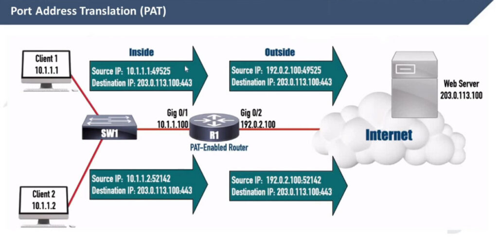
Port Address Translation (PAT), also known as NAT overload, is a type of Network Address Translation (NAT) that allows multiple devices on a local network (with private IP addresses) to share a single public IP address to access external networks, such as the internet.
However, to really understand how PAT works, you must know how TCP/UDP connections are established in the context of IP addresses and ports. Let’s quickly refresh our knowledge of sockets and TCP sessions.
What is a socket, and what is a TCP session?
In networking, a socket is an endpoint for sending and receiving data between devices over a network. It provides a mechanism for communication between two hosts, typically a client and a server, enabling applications to exchange data over protocols like TCP or UDP.
A socket is a pairing between an IP address and a port, as shown below:
IP_Address:Port_Number
When two applications communicate, they each create a socket. A connection between them is established by pairing the client socket with the server socket, forming a TCP or UDP session.
A TCP session is always between two sockets. For example, on Windows, you can see the established sessions between the host and remote hosts using the netstat command, as shown in the output below.
netstat -a -n | find /I "ESTABLISHED"
TCP 10.1.1.1:43000 65.3.2.1:443 ESTABLISHED
TCP 10.1.1.1:43001 65.3.2.1:443 ESTABLISHED
TCP 10.1.1.1:43002 65.3.2.1:443 ESTABLISHED
Notice that a pair of one local and one remote socket uniquely describes a TCP/UDP connection. For example, one unique TCP session is (10.1.1.1:43000-65.3.2.1:443). If host 10.1.1.1 wants to establish a new TCP connection to the same server, it must use another TCP port like this: (10.1.1.1:43001-65.3.2.1:443). The logic is visualized in the diagram below. Notice that PC has established three TCP sessions with the same server. Pay attention to the IP addresses and ports (sockets).
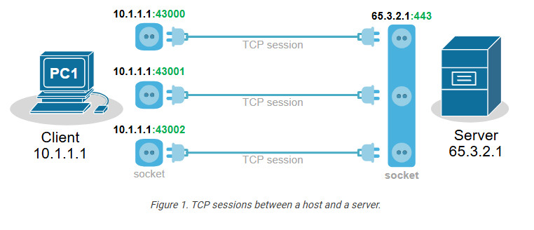
Notice another important aspect. In client-server communications, the server socket is always the same. The server’s web hosting service always listens on the same socket (IP:Port), typically on port 80(http) or 443(https). Therefore, the client-side socket distinguishes the different TCP connections to the server.
Every TCP session is between a pair of sockets. The combination of local and remote sockets is unique because the host uses a different TCP port for each connection. Let’s see a slightly different example – three different hosts establishing a single connection to the same server.
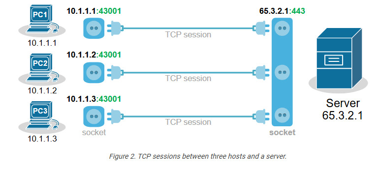
Notice that each host uses the same TCP port. So, how does the server differentiate between the three sessions? Each host’s IP address is different, which makes the three TCP sessions unique from the server’s point of view.
Now, let’s compare the two scenarios from the webserver’s perspective. Do you see any difference in the context of sockets and TCP sessions?
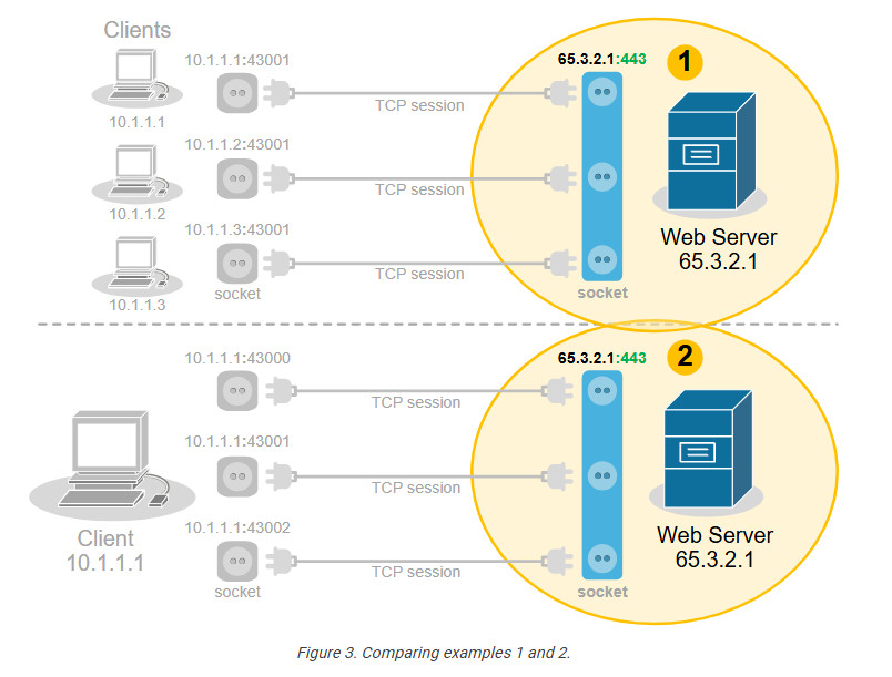
No, from the server’s point of view, there is no difference. In client-server communications, the clients choose a random port and initiate the connection. The server always listens for connection on the same socket. The server does not differentiate between three TCP sessions to one host and three TCP sessions to three different hosts. For the server, these are just three TCP sessions.
What is Port Address Translation (PAT)?
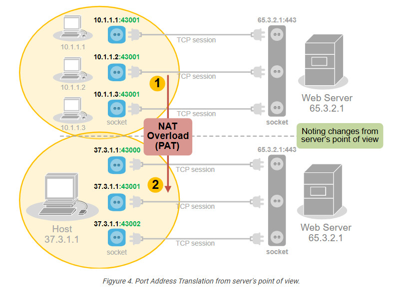
People soon realize they can use this to their advantage and translate multiple clients’ private IP addresses to one public IPv4 address by changing the entire socket (IP:port), not only the IP address. For example, we can change the sockets (IP:port) of the three hosts with different sockets with the same public IPv4 address but different ports. This wouldn’t change anything on the server side.
PAT uses exactly this logic to translate many private IPv4 addresses on the inside with one public IPv4 address on the outside. It takes advantage of the fact that 99% of internet communications are client-server and that the server socket is permanent. In client-server communications, the client initiates the connection and chooses a random port number. The server’s port number is well-known and permanent.
How does PAT work?
Port Address Translation (PAT), also known as NAT Overload, translates many client private addresses to one public IP address, making many TCP sessions from different clients look like many TCP sessions from one client. This does not affect the server side. However, it only works for clients in client-server communications.
For example, the three TCP sessions from PC1, PC2, and PC3 look like three TCP sessions coming from the same host, 37.3.1.1, at the server end, as shown in the diagram below.
Of all Network Address Translation types, PAT is by far the most popular and widely adopted one. Every home WiFi router and every small, medium, and large enterprise uses PAT. It can translate up to 65000 private IPv4 addresses to a single public IPv4 address. It reduces the need for multiple public IP addresses, which can be costly for organizations with many devices.
On the other hand, PAT has some disadvantages as well. It only works for clients in client-server communication (which accounts for 99% of the Internet traffic). It complicates the inbound traffic from outside to inside. For example, generally, with PAT, you cannot have a server on the inside that must be reachable by clients on the outside. In such scenarios, organizations use static one-to-one NAT for the server address, which allows clients on the outside to initiate a connection to the server inside.
Configuring PAT (NAT Overload)
Next, let’s move on to the configuration example. We will use the topology shown in the diagram below. There are three clients that must be able to access the Internet. However, the organization has only one public IPv4 address assigned to the router’s Eth0/1 interface.
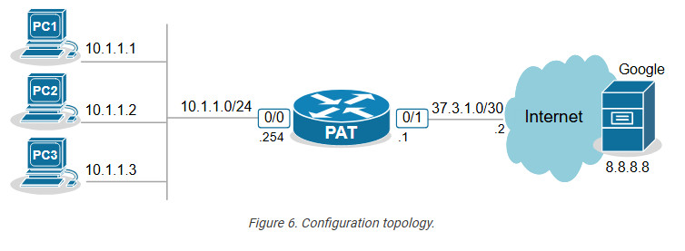
The only way to allow all hosts on the inside to communicate with the outside using one public IP is by using PAT (also called NAT Overload).
The configuration process can be broken down into three steps, as shown in the diagram below.
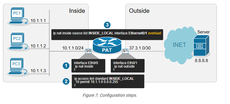
Step 1. Define Inside and Outside
The first step is always the same for every network translation type. We must tell the router which interfaces connect to the inside and which to the outside.
interface Ethernet0/0
ip address 10.1.1.254 255.255.255.0
ip nat inside
!
interface Ethernet0/1
ip address 37.3.1.1 255.255.255.252
ip nat outside
!
We configure interface Eth0/0 as Inside and Eth0/1 as Outside.
Step 2. Define Inside Local criteria
Next, we must configure the Inside Local criteria. Basically, this tells the router which IPv4 addresses it must translate and which not. In our example, we have only one internal subnet and we configure it into an access list named INSIDE_LOCAL.
ip access-list standard INSIDE_LOCAL 10 permit 10.1.1.0 0.0.0.255
However, in real-world examples, an organization may have many inside networks, some of which must be able to pass through the router untranslated and others translated. That’s why this step exists in the process: network admins want to have complete control over which networks the router translates.
Step 3. Configure NAT rules
Lastly, we configure the PAT rule. You can see that the command has several parameters and is a bit long.
ip nat inside source list INSIDE_LOCAL interface Ethernet0/1 overload
Let’s break down and explain each parameter in the command:
Verifying PAT (NAT Overload)
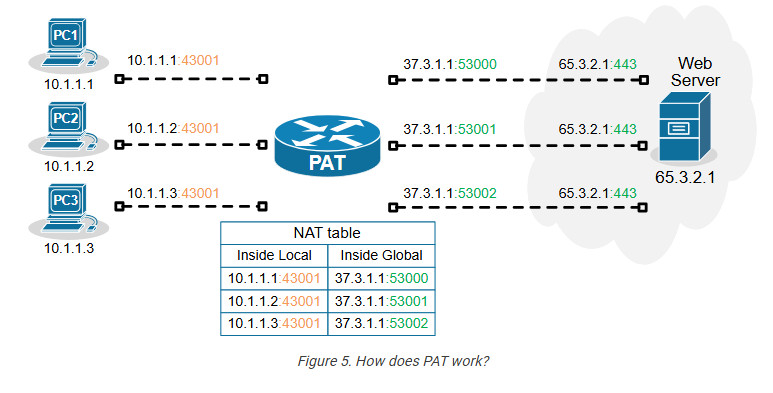
Now, if we initiate some traffic from the clients to the server on the outside, we can see the active translations on the PAT router. Notice the ports used by the clients (in green) and the ports after the translation (in blue). The route has changed the entire socket (IP:port).
NAT# sh ip nat translations
Pro Inside global Inside local Outside local Outside global
tcp 37.3.1.1:4096 10.1.1.1:40591 8.8.8.8:23 8.8.8.8:23
tcp 37.3.1.1:4097 10.1.1.2:49399 8.8.8.8:23 8.8.8.8:23
tcp 37.3.1.1:4098 10.1.1.3:61278 8.8.8.8:23 8.8.8.8:23
We can also gather some useful information using the command below.
NAT# sh ip nat statistics
Total active translations: 3 (0 static, 3 dynamic; 3 extended)
Outside interfaces:
Ethernet0/1
Inside interfaces:
Ethernet0/0
Hits: 140 Misses: 0
CEF Translated packets: 140, CEF Punted packets: 0
Reserved port setting disabled provisioned no
Expired translations: 3
Dynamic mappings:
-- Inside Source
[Id: 1] access-list INSIDE_LOCAL interface Ethernet0/1 refcount 3
nat-limit statistics:
max entry: max allowed 0, used 0, missed 0
Pay attention to the Hits and Misses counters. They indicate how many packets were translated and how many packets weren’t translated because no sockets were available (public IP:available port). This can happen if there are hundreds of clients and only one public IPv4 address on the outside. Recall that there are only 216 port numbers (65536).
Key Takeaways
Port Address Translation (PAT), also known as NAT Overload, is the most widely adopted NAT method in the networking world. It is used in almost every network – home, SOHO, small, medium, or large enterprise. It is the most critical NAT topic that network engineers must understand.
Advantages of PAT (NAT Overload)
Disadvantages of PAT (NAT Overload)
Popularly known as NAT, Network Address Translation is a service that converts a private IP address to a public IP address and vice versa. Until now we have learned how every device that uses the Internet has its IP address.
We have learned about the types of IP addresses, one of them being IPv4 addressing. Imagine if all the devices want their own unique IPv4 addresses. We will run out of unique public IP addresses so fast!
The blame is on the fact that an IPv4 address is only a 32-bit long IP address, therefore there are only 4 billion unique IP addresses. This is why we needed some other alternative to this problem of exhaustible IP addresses!
All thanks to the Network Address Translation (NAT) service. In this blog, we will learn the following Concept:
Note: If you haven’t read the previous blog of our CCNA 200-301 series, I highly recommend you do so.
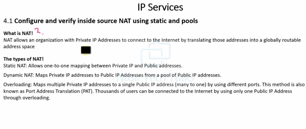
What is NAT (Network Address Translation)?
Network Address Translation, popularly known as NAT, is an outstanding service present in a router. The process of Network Address Translation involves the conversion of private or local IP addresses into global IP addresses and vice versa.
How Does a NAT Service Work? Here’s an Example!
Let us try to understand NAT in a better way with the help of an example. Suppose that you run a company of your own and you need public IPs for your devices. But you can only get one public ID for your company, which in this example is, 150.150.0.1.
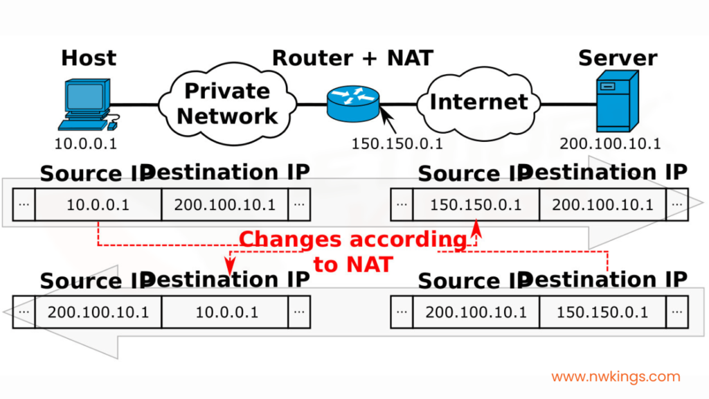
Now, there would be a private network formed along with other devices in your company. If any one host posts a request to visit, for example, facebook.com, the packet would travel from the host with a private IP address, 10.0.0.1 which will be converted by the NAT to the source public IP address of the company, 150.150.0.1. This here is the source IP address.
The destination IP address will be that of facebook.com, which is, 200.100.10.1. When the response is taken back, the source IP address becomes that of Facebook, which is 150.150.0.1, and the destination IP address becomes the public IP address of the company, which is 10.0.0.1.
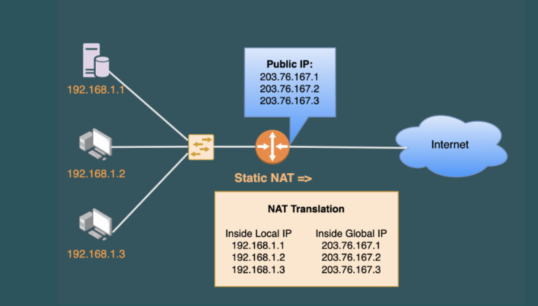
All of this is recorded in a NAT Translation Table. A NAT translation table would look as such for the above example.
Inside Local IP Address | Inside Global IP Address | Outside Global IP Address |
10.0.0.1 | 150.150.0.1 | 200.100.10.1 |
<<<TRANSLATION BY NAT>>> |
You must know that the NAT Translation Table also stores the port numbers of the local IP address and global IP addresses.
Note: the server does not understand the private IP address of the source host. It only understands the public IP address presented by the NAT present in the router.
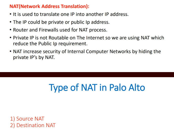
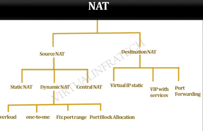
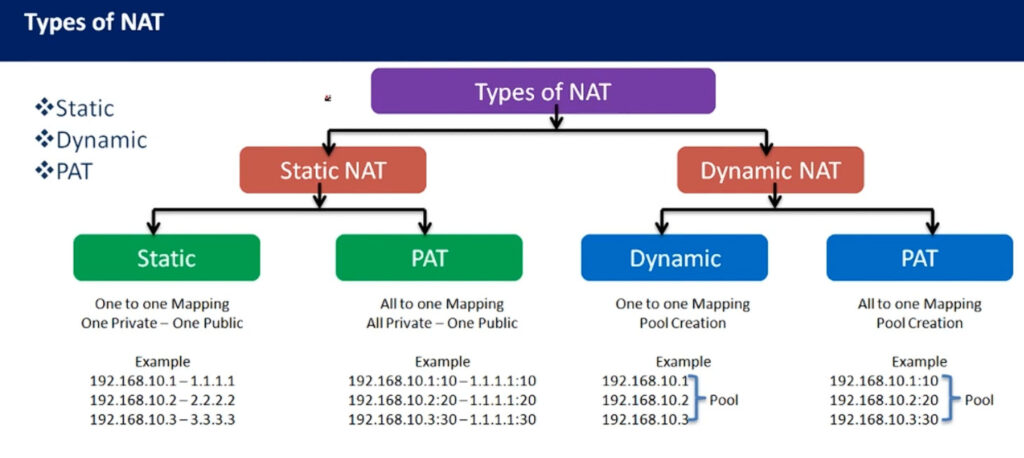
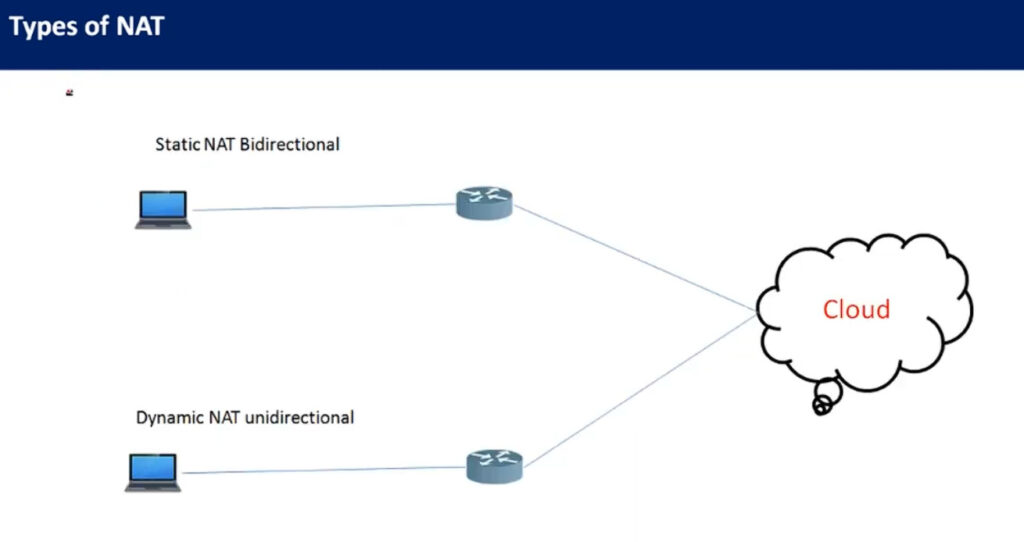
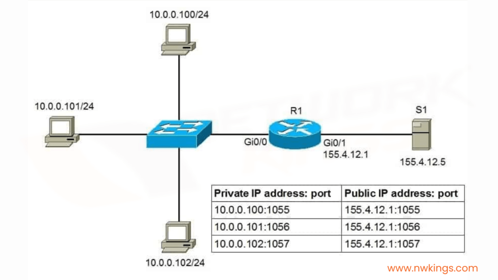
What are the Types of NAT?
There are three types of Network Address Translation. These three types are the methods by which we can configure NAT. The types are as follows:
1. Static NAT:
2. Dynamic NAT:
3. NAT Overloading or Port Address Translation (PAT):
For example, if a particular Data Engineer wants to access the Internet, the NAT will assign a specific port using a Port Address Translation (PAT) table.
What Does the NAT Architecture Look Like?
By now, you must be familiar with the NAT architecture, yet, let’s again look at it briefly.
The NAT architecture consists of two realms:
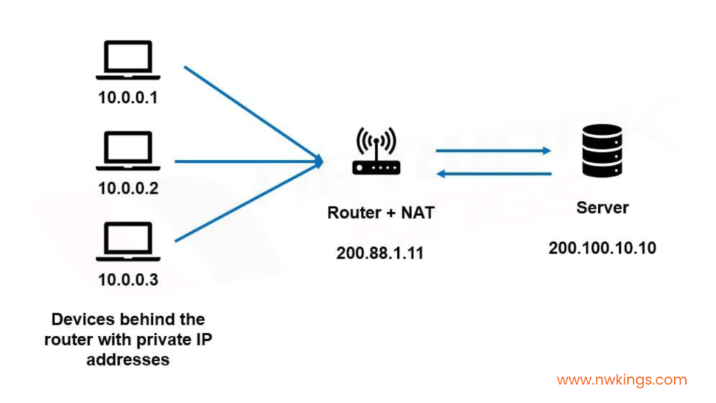
The inside realm consists of the hosts or devices with private IP addresses. The outside realm consists of the server.
The host request travels from the source with a private IP address and it gets converted to a public IP address while reaching the destination IP address via the NAT. Therefore, the NAT functions in a straight line.
What are the Limitations of the NAT?
Let us talk about the limitations of NAT. These are