- 8777701917
- info@saikatinfotech.com
- Basirhat W.B

Router
int port-channel 1
no shutdown
exit

int fa0/0
channel-group 1
no shutdown
exit

int fa0/1
channel-group 1
no shutdown
exit

int port-channel 1
ip add 192.168.1.1 255.255.255.0
no shutdown.
exit

Switch
int range fa0/1-2
channel-group 1 mode on
exit

int port-channel 1
exit
Switch1
interface range fa0/1-2
channel-group 1 mode active

Switch2
interface range fa0/1-2
channel-group 1 mode passive

How To Ether-Channel Checking
show etherchannel summary
show etherchannel detail

show etherchannel port-channel
Switch1
int fa0/1
no switchport
ip address 10.10.10.1 255.255.255.0
no shutdown
exit

hostname sw1

int portchannel 1
no switchport
ip address 172.16.1.1 255.255.255.0
no shutdown
exit

int range fa0/2-3
no switchport
channel-group 1 mode active

Switch2
int fa0/1
no switchport
ip address 11.11.11.1 255.255.255.0
no shutdown
exit
hostname sw2

int portchannel 1
no switchport
ip address 172.16.2.1 255.255.255.0
no shutdown
exit

int range fa0/2-3
no switchport
channel-group 1 mode passive
Router1
int port-channel 1
no shutdown
exit

int fa0/0
channel-group 1
no shutdown
exit

int fa0/1
channel-group 1
no shutdown
exit

int port-channel 1
ip add 192.168.1.1 255.255.255.0
no shutdown.
exit

Router2
int port-channel 1
no shutdown
exit

int fa0/0
channel-group 1
no shutdown
exit

int fa0/1
channel-group 1
no shutdown
exit

int port-channel 1
ip add 192.168.1.1 255.255.255.0
no shutdown
exit
Creating the VLAN in the VLAN Database Switch1

vlan 10
name RED
exit

vlan 20
name ORANGE
exit

vlan 30
name BLUE
exit

Assigning the Switchport to a VLAN

interface Ethernet 0/2
switchport mode access
switchport access vlan 10
exit

interface Ethernet 0/3
switchport mode access
switchport access vlan 30
exit

Creating a trunk port

interface Ethernet 2/1
switchport trunk encapsulation dot1q
switchport mode trunk
exit

interface Ethernet 2/2
switchport trunk encapsulation dot1q
switchport mode trunk
exit

To set the Native VLAN Untag Traffic
interface Ethernet 2/1
switchport trunk native vlan 3
exit

interface Ethernet 2/2
switchport trunk native vlan 3
exit

Allowed VLAN List
interface Ethernet 2/1
switchport trunk allowed vlan 10,20

switchport trunk allowed vlan 20
switchport trunk allowed vlan add 30

interface Ethernet1/1
switchport trunk allowed vlan remove 20

interface Ethernet1/1
no switchport trunk allowed vlan
Switch
show vlan brief <Check VLAN>
show interfaces trunk <Check Trunk Port>
show interfaces switchport
show interfaces status
show spanning-tree

Router
show startup-config
show running-config
show clock
show hosts
show users
show arp
show protocols
show history
show ip route
show version
show ipv6 route
show interfaces
show interfaces gigabitEthernet 0/0
show ip interface brief
show ipv6 interface brief
show cdp neighbors
show ntp status
show Flash:
show logging
show access-lists
show ip dhcp binding
show ip dhcp pool
show ip eigrp neighbors
show ip ospf neighbor
show ip nat translations
show standby
show mac address-table
show spanning tree summary
show etherchannel
show vlan
show vtp status
show port-security
show monitor session all
show interfaces status
show interfaces switchport
show interfaces trunk
Switching Commnd

configure terminal <To log into global configuration mode>
enable <To log into the privileged exec mode>
reload <To reboot the switch>
hostname <To set the hostname>
Copy startup-config running-config <To merge the startup configuration with the configuration in memory>

Copy running-config startup-config <To replace and Save the startup configuration with the startup configuration>
show startup-config <To display startup configuration which is activated when device starts>
show running-config <To display current configuration>
ip address ip-address mask <To assign the specific IP address>
shutdown <To shut the interface>
no shutdown <To bring up the interface>
show ip interface 0/0 <To display the status of a network interface and its IP configurations>
show mac address-table <To show the MAC address table>
show interfaces <To display information about interface (status, counters, and settings)>
show interface status <To display interface line status>
show interfaces switchport <To display configuration settings and operational status>
show cdp <To see if CDP is enabled>
show cdp neighbors[detail] <To list summary of each neighbor connected>
show vlan
show vlan brief <To list every VLAN and its assigned interface >
show port security [interface interface-id] <To display information about security configured on the interface>
Static NAT
Configure the router's  Define inside & Outside

interface fa0/0
ip nat outside

interface fa0/1
ip nat inside

ip nat inside source static 192.168.10.10 202.202.10.1
Dynamic NAT
int f0/0
ip nat outside
exit
int f1/0
ip nat inside
exit

ip nat pool saikat 20.1.1.5 20.1.1.20 netmask 255.255.255.0

access-list 1 permit 192.168.1.0 0.0.0.255

ip nat inside source list 1 pool pool1

show ip nat translations
Dynamic PAT
int f0/0
ip nat outside
exit

int f1/0
ip nat inside
exit

access-list 1 permit 192.168.123.0 0.0.0.255
ip nat inside source list 1 interface fastEthernet 1/0 overload

show ip nat translations
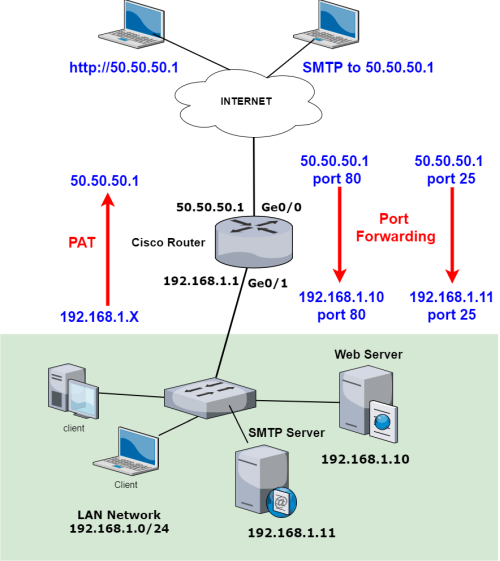
Port Forwarding

WAN Interface
conf t
interface gigabitEthernet 0/0
ip address 50.50.50.1 255.255.255.0
ip nat outside <– Configure the WAN as NAT outside interface
no shutdown
exit

LAN Interface
interface gigabitEthernet 0/1
ip address 192.168.1.1 255.255.255.0
ip nat inside <– Configure the LAN as NAT inside interface
no shutdown
exit

ip route 0.0.0.0 0.0.0.0 50.50.50.2 <– Configure default route

access-list 1 permit 192.168.1.0 0.0.0.255 <– Configure ACL to be used for PAT

ip nat inside source list 1 interface GigabitEthernet0/0 overload <– Configure PAT (NAT overload)

ip nat inside source static tcp 192.168.1.10 80 50.50.50.1 80 <– Port Forwarding for Web Server
ip nat inside source static tcp 192.168.1.11 25 50.50.50.1 25 <– Port Forwarding for SMTP Server

show ip nat translations <---- Checking For NAT Working Or Not
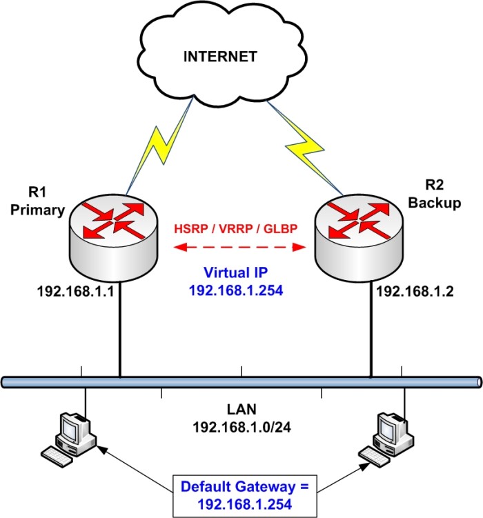

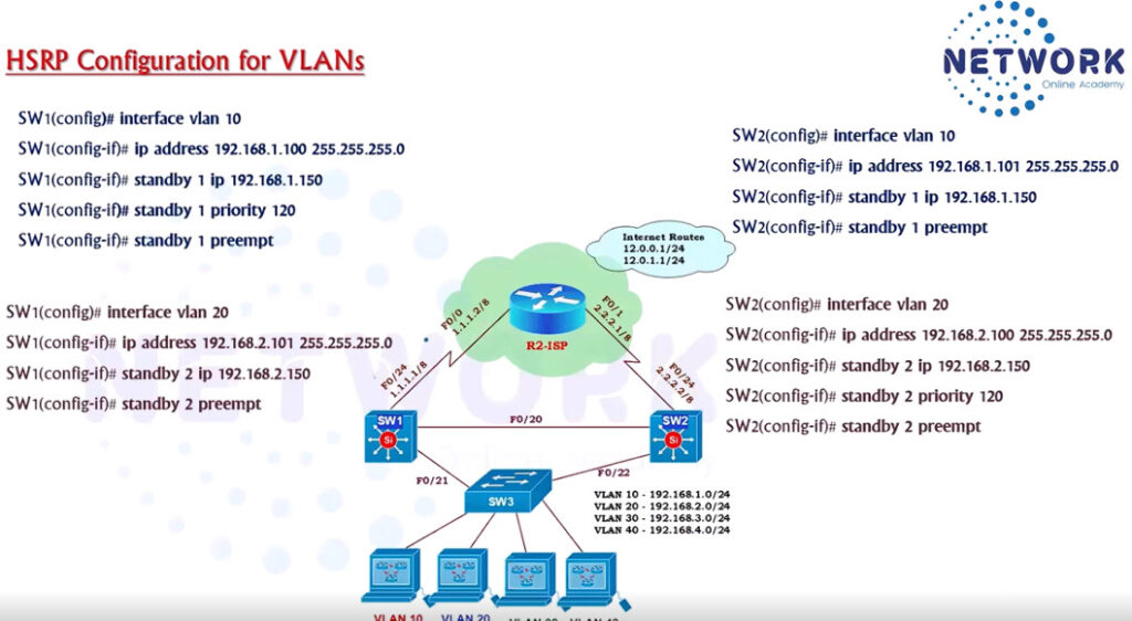
HSRP Configuration
R1
interface Ethernet0/1
description LAN Interface of Active Router
ip address 192.168.1.1 255.255.255.0

standby 1 ip 192.168.1.254 <—- Create HSRP Group 1 and assign Virtual IP

standby 1 priority 101 <—- Assign priority above 100 to make this the primary router

standby 1 preempt <—- Makes router active if it has higher priority
R2
interface Ethernet0/1
description LAN Interface of Standby Router
ip address 192.168.1.2 255.255.255.0
standby 1 ip 192.168.1.254 <—- Create HSRP Group 1 and assign Virtual IP
standby 1 preempt <—- Makes router active if it has higher priority
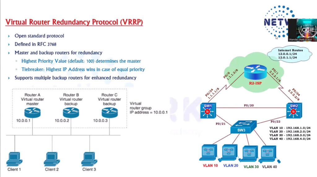
VRRP Configuration
------------------
R1
interface Ethernet0/1
description LAN Interface of Active Routerip address
ip address 192.168.1.1 255.255.255.0
vrrp 1 ip 192.168.1.254 <—- Create VRRP Group 1 and assign Virtual IP
vrrp 1 priority 101 <—- Assign priority above 100 to make this the primary router
vrrp 1 preempt <—- Makes router active if it has higher priority
R2
--
interface Ethernet0/1
description LAN Interface of Standby Router
ip address 192.168.1.2 255.255.255.0
vrrp 1 ip 192.168.1.254 <—- Create VRRP Group 1 and assign Virtual IP
vrrp 1 preempt <—- Makes router active if it has higher priority
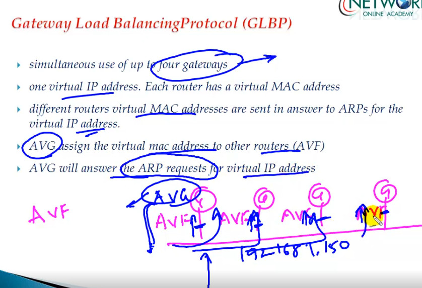
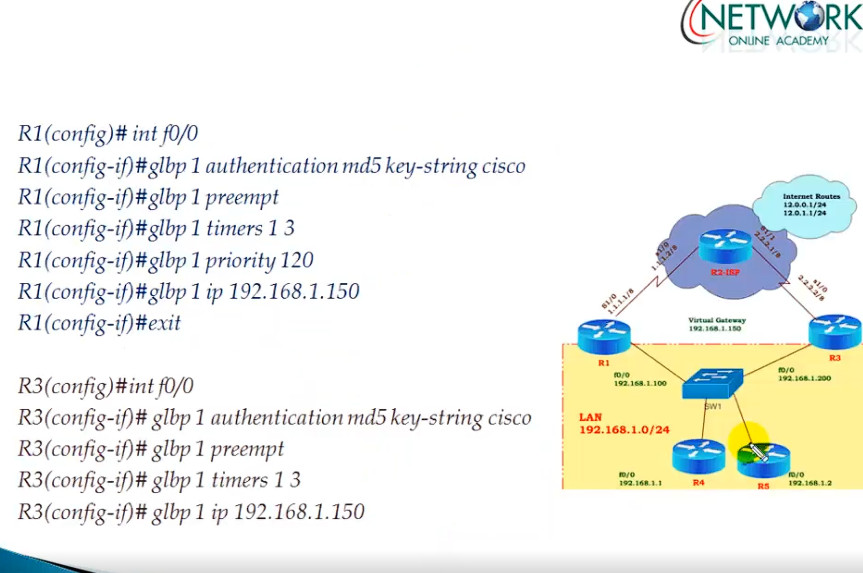
GLBP Configuration
..................
R1
interface Ethernet0/1
description LAN Interface of Primary Router
ip address 192.168.1.1 255.255.255.0
glbp 1 ip 192.168.1.254 <—- Create GLBP Group 1 and assign Virtual IP
glbp 1 priority 101 <—- Assign priority above 100 to make this the primary router
glbp 1 preempt <—- Makes router active if it has higher priority
glbp 1 load-balancing round-robin <—- Configure round-robin balancing of traffic
R2
interface Ethernet0/1
description LAN Interface of Secondary Router
ip address 192.168.1.2 255.255.255.0
glbp 1 ip 192.168.1.254 <—- Create GLBP Group 1 and assign Virtual IP
glbp 1 preempt <—- Makes router active if it has higher priority
glbp 1 load-balancing round-robin <—- Configure round-robin balancing of traffic
Additional Commnd
------------------
show glbp brief
show glbp
Timers – The default hello timer is 3 seconds. The default hold timer is 10 seconds.
R1(config-if)#glbp 10 timers ?
<1-60> Hello interval in seconds
msec Specify hello interval in milliseconds
redirect Specify timeout values for failed forwarders
Authentication – A router will ignore incoming GLBP packets from routers that do not have the same
authentication configuration for a GLBP group.
R1(config-if)#glbp 10 authentication ?
md5 MD5 authentication
text Plain text authentication
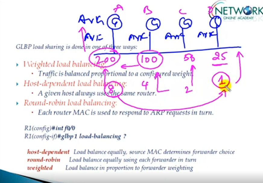
By default, GLBP will load balance traffic using the round-robin method.
But we can change it by using the following command:
R1(config-if)#glbp 10 load-balancing ?
host-dependent Load balance equally, source MAC determines forwarder choice
round-robin Load balance equally using each forwarder in turn
weighted Load balance in proportion to forwarder weighting
Let’s try changing it from round-robin to weighted.
R1(config-if)#glbp 10 load-balancing weighted
R1(config-if)#glbp 10 weighting 50
For verification, let’s use the ‘show glbp’ command.
R1#sh glbp | inc weight
Load balancing: weighted
Active is local, weighting 150
Active is 10.10.10.2 (primary), weighting 100 (expires in 11.424 sec)
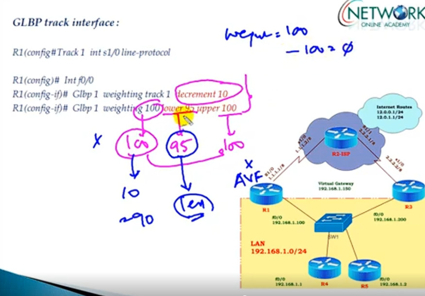
Interface Tracking For ISP Link Router s0/0 Port
track 10 interface s0/0 line-protocol
show track
interface fa0/0
glbp 1 weighting track 10 decrement 10
glbp 1 weighting 120
hostname router-A
!
track 1 interface Serial0/0 line-protocol
!
interface FastEthernet0/0
ip address 192.168.10.1 255.255.255.0
glbp 10 ip 192.168.10.254
glbp 10 priority 255
glbp 10 weighting track 1 decrement 100
!
hostname router-B
!
track 1 interface Serial0/0 line-protocol
!
interface FastEthernet0/0
ip address 192.168.10.2 255.255.255.0
glbp 10 ip 192.168.10.254
glbp 10 priority 254
glbp 10 weighting track 1 decrement 100
!
CDP
---
show cdp
show cdp neighbor
show cdp neighbor detail
Enable CDP
———-
cdp run
Disable CDP
———–
no cdp run
LLDP
—-
show lldp
show lldp neighbor
show lldp neighbor detail
Activate LLDP
—————-
lldp run
no lldp run
Disable/Enable LLDP on Port
—————————
int fa0/1
no lldp transmit
no lldp recive
To configure cdp Hello time and Hold time, you can use the below commands.
Time is mentioned as seconds.
-----------------------------------------------------------
Switch(config)# cdp timer 50
Switch(config)# cdp holdtime 100

To clear the CDP table, use the “clear cdp table” command.
--------------------------------------------------------
Switch# clear cdp table

To verify CDP, you can use general CDP verification commands below:
-------------------------------------------------------------------
Switch# show cdp
Switch# show cdp interface
Switch# show cdp neighbors
Switch# show cdp entry
Switch# show cdp traffic

CDP Disable For Interfaces
--------------------------
fa0/10
no cdp run
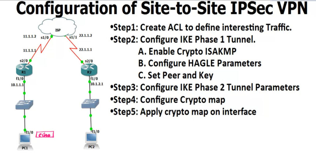
R1
--
access-list 100 permit ip 10.1.1.0 0.0.0.255 10.1.2.0 0.0.0.255

crypto isakmp enable <Phase 1
crypto isakmp policy 1
encr 3des
hash md5
authentication pre-share
group 2
lifetime 8640
exit

crypto isakmp key 0 HQoffice address 22.1.1.1 <-R2 Public IP

crypto ipsec transform-set TS esp-3des esp-md5-hmac <IPSEC Tunnel Create
crypto map CMAP 10 ipsec-isakmp
set peer 12.1.1.1
set transform-set TS
match address 100


interface s2/0 <-Enable IPsec Router Interfaces
crypto map CMAP

ping 12.1.1.10 repeat 10000

IPsec Checking Commnd
---------------------
show crypto isakmp policy <-Checking Policy
show crypto isakmp key <-Checking key
show crypto ipsec transform-set
show crypto map
show crypto isakmp sa <-Checking Phase 1 Status
show crypto ipsec sa <-Checking Phase 2


R2
--
access-list 100 permit ip 10.1.2.0 0.0.0.255 10.1.1.0 0.0.0.255

crypto isakmp enable
crypto isakmp policy 1
encr 3des
hash md5
authentication pre-share
group 2
lifetime 8640
exit

crypto isakmp key 0 HQoffice address 11.1.1.1 <-R1 Public IP

crypto ipsec transform-set TS esp-3des esp-md5-hmac
crypto map CMAP 10 ipsec-isakmp
set peer 12.1.1.1
set transform-set TS
match address 100

interface s2/0
crypto map CMAP
config t
ip dhcp pool 10 <For VLAN 10>
network 10.10.10.0 255.255.255.0
default router 10.10.10.1
dns-server 8.8.8.8
exit

config t
ip dhcp pool 20
network 10.10.20.0 255.255.255.0
default router 10.10.20.1
dns-server 8.8.8.8
exit

config t
ip dhcp pool 30
network 10.10.30.0 255.255.255.0
default router 10.10.30.1
dns-server 8.8.8.8
exit
ip dhcp excluded-address 192.168.2.0 192.168.2.10
ip dhcp pool Saikat Infotech
default-router 192.168.2.1
dns-server 192.168.2.2
network 192.168.2.0 255.255.255.0
exit
============================================================
How To Configration DM-VPN Hub Phase - 1 - Branch Router ?
============================================================
-R1-Router-Hub-HQ-Office------------------------------------
Step #1 interface tunnel 1
Step #2 ip address 40.40.40.1 255.255.255.0 <Hub-Tunnel-Private-IP-Gateway>
Step #3 tunnel source fa0/0
Step #4 tunnel mode gre multipoint
Step #5 ip nhrp network id 123
Step #6 ip nhrp map multicast dynamic
Step #7 no ip split-horizon eigrp 10

===========================================================
How To Configration DM-VPN Hub Phase - 2 - Branch Router ?
===========================================================
-R1-Router-Hub-HQ-Office-----------------------------------
Step #1 interface tunnel 1
Step #2 ip address 40.40.40.1 255.255.255.0 <Hub-Tunnel-Private-IP-Gateway>
Step #3 tunnel source fa0/0
Step #4 tunnel mode gre multipoint
Step #5 ip nhrp network id 123
Step #5 ip nhrp authentication saikat
Step #5 ip nhrp holdtime 300
Step #6 ip nhrp map multicast dynamic
Step #7 no ip split-horizon eigrp 10
Step #8 no ip next hop self eigrp 10 <Spoke To Spoke Reach With Out Hub >

==========================================================================
How To Configration DM-VPN Spoke Phase - 1 - Branch Router ?
==========================================================================
-R2-Router-Spoke-2--------------------------------------------------------
Step #1 interface tunnel 1
Step #2 ip address 40.40.40.2 255.255.255.0
Step #3 tunnel source fa0/0
Step #4 tunnel destination 203.202.2.2 <R1-Hub-Public-IP>
Step #5 ip nhrp network id 123
Step #6 ip nhrp nhs 40.40.40.1 <Hub-Tunnel-Private-IP-Gateway>
Step #7 Exit
==========================================================================
How To Configration DM-VPN Spoke Phase - 2 - Branch Router ?
==========================================================================
-R2-Router-Spoke-2--------------------------------------------------------
Step #1 interface tunnel 1
Step #2 ip address 40.40.40.2 255.255.255.0
Step #3 tunnel source fa0/0
Step #4 tunnel mode gre multipoint
Step #5 ip nhrp network id 123
Step #6 ip nhrp authentication saikat <Password Protect Hub Router>
Step #7 ip nhrp holdtime 300
Step #6 ip nhrp map multicast 203.202.2.2 <Hub-Public-IP>
Step #7 ip nhrp nhs 40.40.40.1 <Hub-Tunnel-Private-IP-Gateway>
Step #8 ip nhrp map 40.40.40.1 203.202.2.2 <Hub-Public-IP>

=======================================================================
How To Configration DM-VPN Duel Hub Phase - 2 - Branch Router ?
=======================================================================
Step #01 Same Configration DM-VPN Hub <Changes From Spoke Router For Duel Hub NHS Server>
==================================================================================
How To Configration DM-VPN Spoke Phase - 2 Duel Hub 2 Nhs Server - Branch Router ?
==================================================================================
-R1-Router-Spoke-1---------------
Step #1 interface tunnel 1
Step #2 ip address 40.40.40.2 255.255.255.0
Step #3 tunnel source fa0/0
Step #4 tunnel mode gre multipoint
Step #5 ip nhrp network id 123
Step #6 ip nhrp map multicast 203.202.2.2 <Hub-Static-Public-IP-1>
Step #7 ip nhrp map multicast 203.202.2.3 <Hub-Static-Public-IP-2>
Step #8 ip nhrp nhs 40.40.40.1 <Hub-Tunnel-Private-IP-Gateway-Server-1>
Step #9 ip nhrp nhs 40.40.40.5 <Hub-Tunnel-Private-IP-Gateway-Server -2>
Step #10 ip nhrp map 40.40.40.1 203.202.2.2 <Hub-Public-IP>
Step #11 ip nhrp registration timeout 5
Step #12 ip nhrp holdtime 20
--Showing-----Commnd-------DM---VPN---------
Step #1 show ip nhrp nhs
Step #2 clear ip nhrp
Step #2 show ip nhrp
Step #3 show run int tunnel 0
How To Configration GRE-VPN Tunnel
R1-Router-HQ-Branch
Step #1 interface tunnel 1
Step #2 ip address 40.40.40.1 255.255.255.0
Step #3 tunnel source fa0/0
Step #4 tunnel destination 203.202.2.2 <R2-Public-I
R2-Router-Branch-Office
Step #1 interface tunnel 1
Ste  ip address 40.40.40.2 255.255.255.0
Step #3 tunnel source fa0/0
Step #4 tunnel destination 203.202.100.100 <R1-Public-IP>

Optional
Step #5 int tunnel 0
Step #6 ip mtu 1400
Step #7 ip tcp adjust-mss 1360

How To Configure GRE-VPN IP-Sec Policy ?
R1-Router-HQ-Office
Step #1 crypto isakmp policy 10
Step #2 authentication pre-share
Step #3 encryption 3des
Step #4 hash md5
Step #5 group 2
Step #6 exit
Step #7 crypto isakmp key saikat address 203.202.100.100 <Remote Public IP -R2-Router-Branch-Office>
Step #8 crypto ipsec transform-set saikat123 esp-sha-hmac esp-3des
Step #9 mode transparent
Step #10 exit
Step #11 crypto ipsec profile CCNP
Step #12 set transform-set saikat123

R2-Router-Branch-Office
Step #1 crypto isakmp policy 10
Step #2 authentication pre-share
Step #3 encryption 3des
Step #4 hash md5
Step #5 group 2
Step #6 exit
Step #7 crypto isakmp key saikat address 203.202.100.100 <Remote Public IP -R1-Router-HQ-Office>
Step #8 crypto ipsec transform-set saikat123 esp-sha-hmac esp-3des
Step #9 mode transparent
Step #10 exit
Step #11 crypto ipsec profile CCNP
Step #12 set transform-set saikat123


IP-SEC Policy Apply GRE-VPN Tunnel Interface 1 ?
Step #5 int tunnel 1
Step #6 tunnel protection ipsec profile CCNP
int fa0/0
ip address 192.168.1.2 255.255.255.0
no shut
exit

int loopback 0
ip address 1.1.1.1 255.255.255.255

show ip route

router ospf 1
network 0.0.0.0 255.255.255.255 area 0 <1 Commnd OSPF Run All Interfaces>
int fa0/0
ip address 192.168.2.2 255.255.255.0
no shut
exit
int loopback 0
ip address 2.2.2.2 255.255.255.255
show ip route
router ospf 1
network 0.0.0.0 255.255.255.255 area 0 <1 Commnd OSPF Run All Interfaces>
int fa0/0
ip address 192.168.3.2 255.255.255.0
no shut
exit

int loopback 0
ip address 3.3.3.1 255.255.255.255

show ip route

router ospf 1
network 0.0.0.0 255.255.255.255 area 0 <1 Commnd OSPF Run All Interfaces>
int fa0/0
ip address 192.168.4.2 255.255.255.0
no shut
exit

int loopback 0
ip address 4.4.4.1 255.255.255.255

show ip route

router ospf 1
network 0.0.0.0 255.255.255.255 area 0 <1 Commnd OSPF Run All Interfaces>
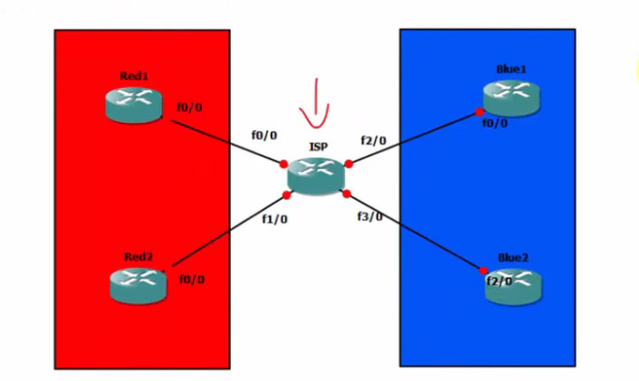
ISP Router Config
ip vrf RED
exit
ip vrf BLUE
exit

show ip vrf


Red Customar Config
interface FastEthernet 0/0
ip vrf forwarding RED
ip address 192.168.1.1 255.255.255.0
no shut
exit

router ospf 1 vrf RED
network 192.168.1.0 0.0.0.255 area 0
network 192.168.2.0 0.0.0.255 area 0

interface FastEthernet 1/0
ip vrf forwarding RED
ip address 192.168.2.1 255.255.255.0
no shut
exit

show ip vrf RED
show ip vrf


Blue Customar Config

interface FastEthernet 2/0
ip vrf forwarding BLUE
ip address 192.168.3.1 255.255.255.0
no shut
exit

router ospf 1 vrf BLUE
network 192.168.3.0 0.0.0.255 area 0
network 192.168.4.0 0.0.0.255 area 0

interface FastEthernet 3/0
ip vrf forwarding BLUE
ip address 192.168.4.1 255.255.255.0
no shut
exit


show ip vrf RED
show ip vrf