- 8777701917
- info@saikatinfotech.com
- Basirhat W.B

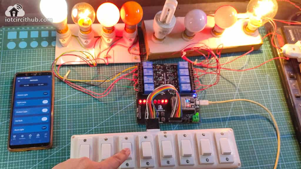
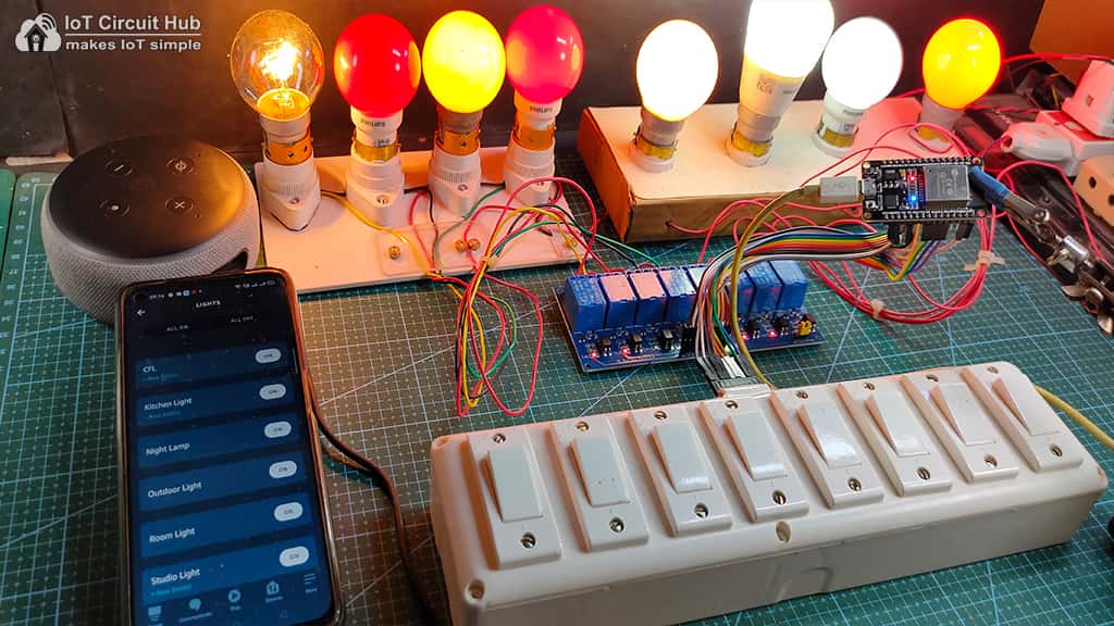
In this ESP32 project, I have shown how to make an ESP32 Alexa home automation system with Echo DOT, manual switches, relay module, and ESP32. I have used Amazon Alexa App to control the home appliances with voice commands for this Alexa automation project.
If there is no internet, still you can also control the home appliances from the pushbuttons and when the internet comes back the ESP32 will automatically connect with the WiFi.
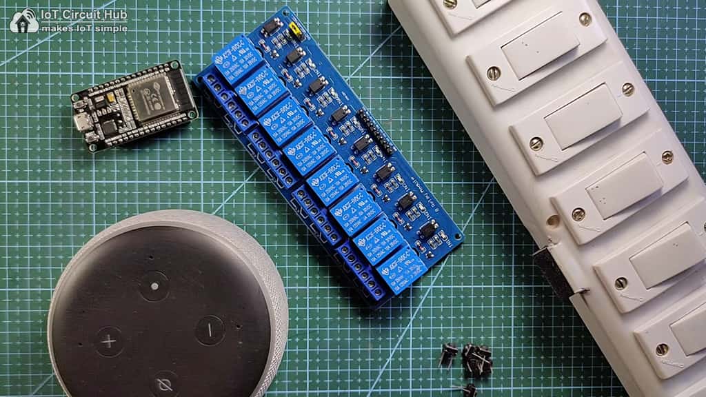
For this IoT project, I have not used any third-party IoT applications and you don’t need any custom design PCB for this project. So you can easily make this amazon echo home automation system at home.
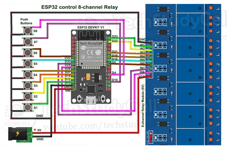
The circuit is very simple, I have used D23, D22, D21, D19, D18, D5, D25 & D26 GPIO to control the 8-channel relay module.
And the GPIO D13, D12, D14, D27, D33, D32, D15 & D4 are connected with manual switches to control the relay module manually.
I have used the INPUT_PULLUP function in Arduino IDE instead of using the pull-up resistors with each switch.
As per the source code, when the control pins of the relay module receive the LOW signal the respective relay will turn on and the relay will turn off for the HIGH signal in the control pin.
I have used a 5V 2Amp mobile charger to supply the circuit.
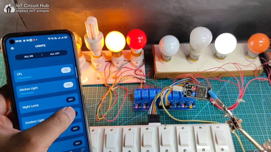
If the ESP32 is connected with WiFi, then you can control the relay module from Amazon Alexa App and manual switches. You can control and monitor the current status of the switches in the Alexa App.
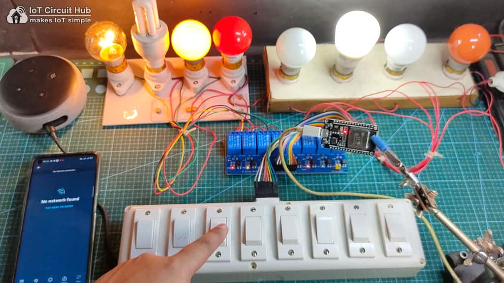
If the WiFi is not available, you can control the relays from the switches manually.
The ESP32 will check for the WiFi after every 3 seconds. When the internet comes back, the ESP32 will automatically connect with the WiFi.
In the Tutorial video, I have explained all the steps to program the ESP32 DEV KIT V1 using Arduino IDE.
#include <WiFi.h>
#include <Espalexa.h>
#include <AceButton.h>
using namespace ace_button;

Espalexa espalexa;

// define the GPIO connected with Relays and switches
#define RelayPin1 23  //D23
#define RelayPin2 22  //D22
#define RelayPin3 21  //D21
#define RelayPin4 19  //D19
#define RelayPin5 18  //D18
#define RelayPin6 5   //D5
#define RelayPin7 25  //D25
#define RelayPin8 26  //D26

#define SwitchPin1 13  //D13
#define SwitchPin2 12  //D12
#define SwitchPin3 14  //D14
#define SwitchPin4 27  //D27
#define SwitchPin5 33  //D33
#define SwitchPin6 32  //D32
#define SwitchPin7 15  //D15
#define SwitchPin8 4   //D4

#define wifiLed    2   //D2

// WiFi Credentials
const char* ssid = "WiFi Name";
const char* password = "WiFi Password";

// device names
String Device_1_Name = "Study Lamp";
String Device_2_Name = "CFL";
String Device_3_Name = "Yellow light";
String Device_4_Name = "Night Lamp";
String Device_5_Name = "Studio Light";
String Device_6_Name = "Outdoor Light";
String Device_7_Name = "Kitchen Light";
String Device_8_Name = "Room Light";

// prototypes
boolean connectWifi();

//callback functions
void firstLightChanged(uint8_t brightness);
void secondLightChanged(uint8_t brightness);
void thirdLightChanged(uint8_t brightness);
void fourthLightChanged(uint8_t brightness);
void fifthLightChanged(uint8_t brightness);
void sixthLightChanged(uint8_t brightness);
void senventhLightChanged(uint8_t brightness);
void eighthLightChanged(uint8_t brightness);

ButtonConfig config1;
AceButton button1(&config1);
ButtonConfig config2;
AceButton button2(&config2);
ButtonConfig config3;
AceButton button3(&config3);
ButtonConfig config4;
AceButton button4(&config4);
ButtonConfig config5;
AceButton button5(&config5);
ButtonConfig config6;
AceButton button6(&config6);
ButtonConfig config7;
AceButton button7(&config7);
ButtonConfig config8;
AceButton button8(&config8);

void handleEvent1(AceButton*, uint8_t, uint8_t);
void handleEvent2(AceButton*, uint8_t, uint8_t);
void handleEvent3(AceButton*, uint8_t, uint8_t);
void handleEvent4(AceButton*, uint8_t, uint8_t);
void handleEvent5(AceButton*, uint8_t, uint8_t);
void handleEvent6(AceButton*, uint8_t, uint8_t);
void handleEvent7(AceButton*, uint8_t, uint8_t);
void handleEvent8(AceButton*, uint8_t, uint8_t);

boolean wifiConnected = false;

//our callback functions
void firstLightChanged(uint8_t brightness)
{
  //Control the device
  if (brightness == 255)
    {
      digitalWrite(RelayPin1, LOW);
      Serial.println("Device1 ON");
    }
  else
  {
    digitalWrite(RelayPin1, HIGH);
    Serial.println("Device1 OFF");
  }
}

void secondLightChanged(uint8_t brightness)
{
  //Control the device
  if (brightness == 255)
    {
      digitalWrite(RelayPin2, LOW);
      Serial.println("Device2 ON");
    }
  else
  {
    digitalWrite(RelayPin2, HIGH);
    Serial.println("Device2 OFF");
  }
}

void thirdLightChanged(uint8_t brightness)
{
  //Control the device
  if (brightness == 255)
    {
      digitalWrite(RelayPin3, LOW);
      Serial.println("Device3 ON");
    }
  else
  {
    digitalWrite(RelayPin3, HIGH);
    Serial.println("Device3 OFF");
  }
}

void fourthLightChanged(uint8_t brightness)
{
  //Control the device
  if (brightness == 255)
    {
      digitalWrite(RelayPin4, LOW);
      Serial.println("Device4 ON");
    }
  else
  {
    digitalWrite(RelayPin4, HIGH);
    Serial.println("Device4 OFF");
  }
}

void fifthLightChanged(uint8_t brightness)
{
  //Control the device
  if (brightness == 255)
    {
      digitalWrite(RelayPin5, LOW);
      Serial.println("Device5 ON");
    }
  else
  {
    digitalWrite(RelayPin5, HIGH);
    Serial.println("Device1 OFF");
  }
}

void sixthLightChanged(uint8_t brightness)
{
  //Control the device
  if (brightness == 255)
    {
      digitalWrite(RelayPin6, LOW);
      Serial.println("Device6 ON");
    }
  else
  {
    digitalWrite(RelayPin6, HIGH);
    Serial.println("Device6 OFF");
  }
}

void seventhLightChanged(uint8_t brightness)
{
  //Control the device
  if (brightness == 255)
    {
      digitalWrite(RelayPin7, LOW);
      Serial.println("Device7 ON");
    }
  else
  {
    digitalWrite(RelayPin7, HIGH);
    Serial.println("Device7 OFF");
  }
}

void eighthLightChanged(uint8_t brightness)
{
  //Control the device
  if (brightness == 255)
    {
      digitalWrite(RelayPin8, LOW);
      Serial.println("Device8 ON");
    }
  else
  {
    digitalWrite(RelayPin8, HIGH);
    Serial.println("Device8 OFF");
  }
}

// connect to wifi – returns true if successful or false if not
boolean connectWifi()
{
  boolean state = true;
  int i = 0;

  WiFi.mode(WIFI_STA);
  WiFi.begin(ssid, password);
  Serial.println("");
  Serial.println("Connecting to WiFi");

  // Wait for connection
  Serial.print("Connecting...");
  while (WiFi.status() != WL_CONNECTED) {
    delay(500);
    Serial.print(".");
    if (i > 20) {
      state = false; break;
    }
    i++;
  }
  Serial.println("");
  if (state) {
    Serial.print("Connected to ");
    Serial.println(ssid);
    Serial.print("IP address: ");
    Serial.println(WiFi.localIP());
  }
  else {
    Serial.println("Connection failed.");
  }
  return state;
}

void addDevices(){
  // Define your devices here.
  espalexa.addDevice(Device_1_Name, firstLightChanged); //simplest definition, default state off
  espalexa.addDevice(Device_2_Name, secondLightChanged);
  espalexa.addDevice(Device_3_Name, thirdLightChanged);
  espalexa.addDevice(Device_4_Name, fourthLightChanged);
  espalexa.addDevice(Device_5_Name, fifthLightChanged);
  espalexa.addDevice(Device_6_Name, sixthLightChanged);
  espalexa.addDevice(Device_7_Name, seventhLightChanged);
  espalexa.addDevice(Device_8_Name, eighthLightChanged);

  espalexa.begin();
}

void setup()
{
  Serial.begin(115200);

  pinMode(RelayPin1, OUTPUT);
  pinMode(RelayPin2, OUTPUT);
  pinMode(RelayPin3, OUTPUT);
  pinMode(RelayPin4, OUTPUT);
  pinMode(RelayPin5, OUTPUT);
  pinMode(RelayPin6, OUTPUT);
  pinMode(RelayPin7, OUTPUT);
  pinMode(RelayPin8, OUTPUT);

  pinMode(wifiLed, OUTPUT);

  pinMode(SwitchPin1, INPUT_PULLUP);
  pinMode(SwitchPin2, INPUT_PULLUP);
  pinMode(SwitchPin3, INPUT_PULLUP);
  pinMode(SwitchPin4, INPUT_PULLUP);
  pinMode(SwitchPin5, INPUT_PULLUP);
  pinMode(SwitchPin6, INPUT_PULLUP);
  pinMode(SwitchPin7, INPUT_PULLUP);
  pinMode(SwitchPin8, INPUT_PULLUP);

  //During Starting all Relays should TURN OFF
  digitalWrite(RelayPin1, HIGH);
  digitalWrite(RelayPin2, HIGH);
  digitalWrite(RelayPin3, HIGH);
  digitalWrite(RelayPin4, HIGH);
  digitalWrite(RelayPin5, HIGH);
  digitalWrite(RelayPin6, HIGH);
  digitalWrite(RelayPin7, HIGH);
  digitalWrite(RelayPin8, HIGH);

  config1.setEventHandler(button1Handler);
  config2.setEventHandler(button2Handler);
  config3.setEventHandler(button3Handler);
  config4.setEventHandler(button4Handler);
  config5.setEventHandler(button5Handler);
  config6.setEventHandler(button6Handler);
  config7.setEventHandler(button7Handler);
  config8.setEventHandler(button8Handler);

  button1.init(SwitchPin1);
  button2.init(SwitchPin2);
  button3.init(SwitchPin3);
  button4.init(SwitchPin4);
  button5.init(SwitchPin5);
  button6.init(SwitchPin6);
  button7.init(SwitchPin7);
  button8.init(SwitchPin8);


  // Initialise wifi connection
  wifiConnected = connectWifi();

  if (wifiConnected)
  {
    addDevices();
  }
  else
  {
    Serial.println("Cannot connect to WiFi. So in Manual Mode");
    delay(1000);
  }
}

void loop()
{
   if (WiFi.status() != WL_CONNECTED)
  {
    //Serial.print("WiFi Not Connected ");
    digitalWrite(wifiLed, LOW); //Turn off WiFi LED
  }
  else
  {
    //Serial.print("WiFi Connected  ");
    digitalWrite(wifiLed, HIGH);
    //Manual Switch Control
    //WiFi Control
    if (wifiConnected){
      espalexa.loop();
      delay(1);
    }
    else {
      wifiConnected = connectWifi(); // Initialise wifi connection
      if(wifiConnected){
      addDevices();
      }
    }
  }
  button1.check();
  button2.check();
  button3.check();
  button4.check();
  button5.check();
  button6.check();
  button7.check();
  button8.check();
}

void button1Handler(AceButton* button, uint8_t eventType, uint8_t buttonState) {
  Serial.println("EVENT1");
  EspalexaDevice* d1 = espalexa.getDevice(0); //this will get "first device", the index is zero-based
  switch (eventType) {
    case AceButton::kEventPressed:
      Serial.println("kEventPressed");
      d1->setPercent(100); //set value "brightness" in percent
      digitalWrite(RelayPin1, LOW);
      break;
    case AceButton::kEventReleased:
      Serial.println("kEventReleased");
      d1->setPercent(0); //set value "brightness" in percent
      digitalWrite(RelayPin1, HIGH);
      break;
  }
}

void button2Handler(AceButton* button, uint8_t eventType, uint8_t buttonState) {
  Serial.println("EVENT2");
  EspalexaDevice* d2 = espalexa.getDevice(1);
  switch (eventType) {
    case AceButton::kEventPressed:
      Serial.println("kEventPressed");
      d2->setPercent(100);
      digitalWrite(RelayPin2, LOW);
      break;
    case AceButton::kEventReleased:
      Serial.println("kEventReleased");
      d2->setPercent(0);
      digitalWrite(RelayPin2, HIGH);
      break;
  }
}

void button3Handler(AceButton* button, uint8_t eventType, uint8_t buttonState) {
  Serial.println("EVENT3");
  EspalexaDevice* d3 = espalexa.getDevice(2);
  switch (eventType) {
    case AceButton::kEventPressed:
      Serial.println("kEventPressed");
      d3->setPercent(100);
      digitalWrite(RelayPin3, LOW);
      break;
    case AceButton::kEventReleased:
      Serial.println("kEventReleased");
      d3->setPercent(0);
      digitalWrite(RelayPin3, HIGH);
      break;
  }
}

void button4Handler(AceButton* button, uint8_t eventType, uint8_t buttonState) {
  Serial.println("EVENT4");
  EspalexaDevice* d4 = espalexa.getDevice(3);
  switch (eventType) {
    case AceButton::kEventPressed:
      Serial.println("kEventPressed");
      d4->setPercent(100);
      digitalWrite(RelayPin4, LOW);
      break;
    case AceButton::kEventReleased:
      Serial.println("kEventReleased");
      d4->setPercent(0);
      digitalWrite(RelayPin4, HIGH);
      break;
  }
}

void button5Handler(AceButton* button, uint8_t eventType, uint8_t buttonState) {
  Serial.println("EVENT5");
  EspalexaDevice* d5 = espalexa.getDevice(4);
  switch (eventType) {
    case AceButton::kEventPressed:
      Serial.println("kEventPressed");
      d5->setPercent(100);
      digitalWrite(RelayPin5, LOW);
      break;
    case AceButton::kEventReleased:
      Serial.println("kEventReleased");
      d5->setPercent(0);
      digitalWrite(RelayPin5, HIGH);
      break;
  }
}

void button6Handler(AceButton* button, uint8_t eventType, uint8_t buttonState) {
  Serial.println("EVENT6");
  EspalexaDevice* d6 = espalexa.getDevice(5);
  switch (eventType) {
    case AceButton::kEventPressed:
      Serial.println("kEventPressed");
      d6->setPercent(100);
      digitalWrite(RelayPin6, LOW);
      break;
    case AceButton::kEventReleased:
      Serial.println("kEventReleased");
      d6->setPercent(0);
      digitalWrite(RelayPin6, HIGH);
      break;
  }
}

void button7Handler(AceButton* button, uint8_t eventType, uint8_t buttonState) {
  Serial.println("EVENT7");
  EspalexaDevice* d7 = espalexa.getDevice(6);
  switch (eventType) {
    case AceButton::kEventPressed:
      Serial.println("kEventPressed");
      d7->setPercent(100);
      digitalWrite(RelayPin7, LOW);
      break;
    case AceButton::kEventReleased:
      Serial.println("kEventReleased");
      d7->setPercent(0);
      digitalWrite(RelayPin7, HIGH);
      break;
  }
}

void button8Handler(AceButton* button, uint8_t eventType, uint8_t buttonState) {
  Serial.println("EVENT8");
  EspalexaDevice* d8 = espalexa.getDevice(7);
  switch (eventType) {
    case AceButton::kEventPressed:
      Serial.println("kEventPressed");
      d8->setPercent(100);
      digitalWrite(RelayPin8, LOW);
      break;
    case AceButton::kEventReleased:
      Serial.println("kEventReleased");
      d8->setPercent(0);
      digitalWrite(RelayPin8, HIGH);
      break;
  }
}
Enter the following WiFi credential in the code:
Now select the board as DOIT ESP32 DEVKIT V1 and the PORT in Arduino IDE. Then click on the upload button to program the ESP32 board.
After uploading the code, if the ESP32 connects with internet, the blue LED should turn on.
Password”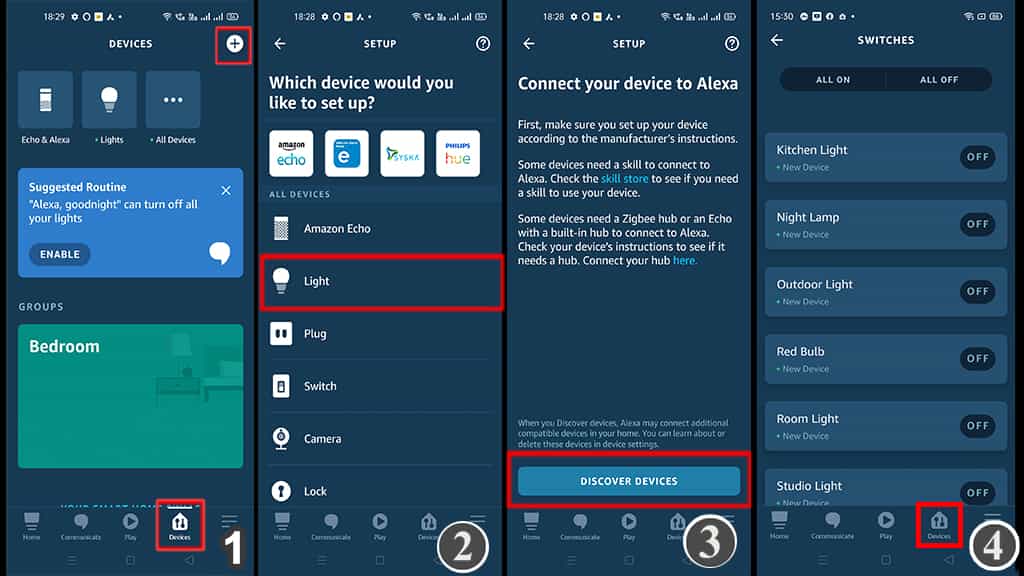
While configuring the Amazon Alexa App, the ESP32, Amazon Echo dot and the smartphone should be connected to same the wifi network.
Once the Alexa App found all the devices, you can control those devices with voice commands using the Alexa echo dot.
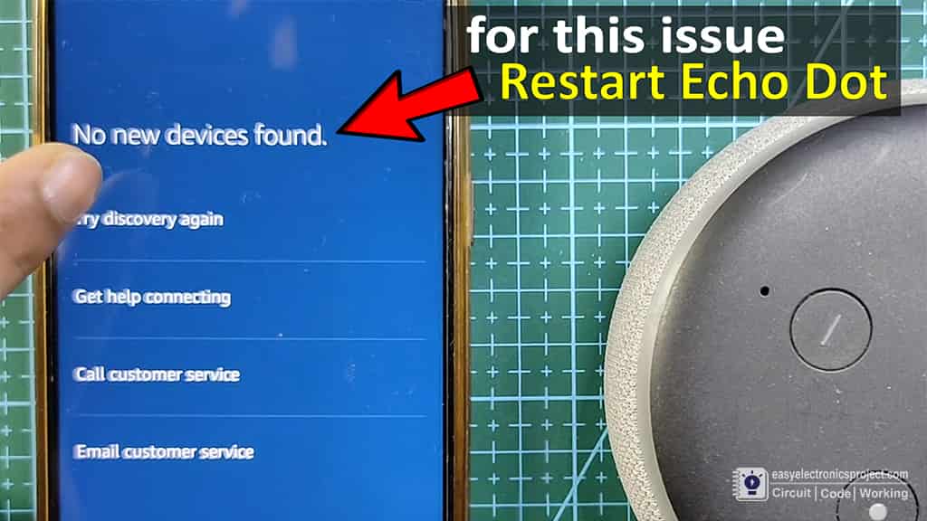
You may face No new devices found error while adding the devices with Alexa.
Then restart the echo dot, after restart once the echo dot connects with the same WiFi, tap on “Try discovery again”.
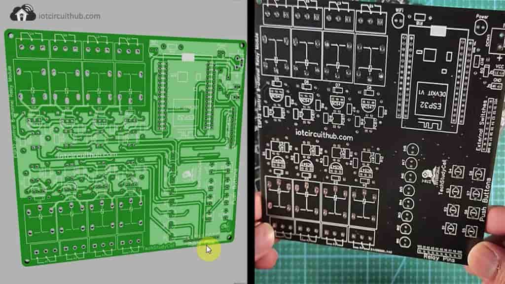
To give the project a professional look and make the circuit compact, I have designed a PCB for this ESP32 home automation project. This PCB can be used for any ESP32 Home Automation project.
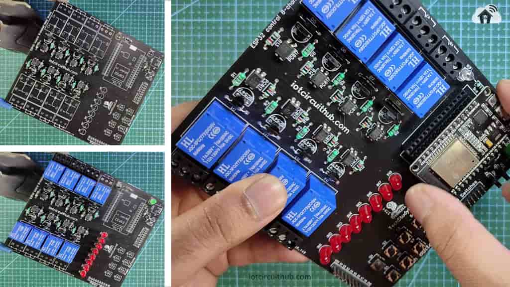
Solder all the components as mentioned on the PCB.
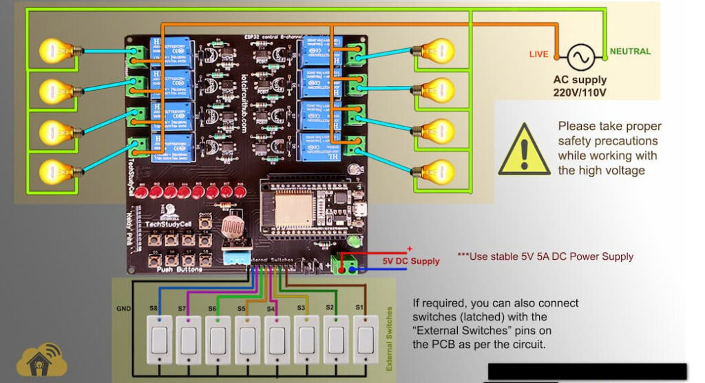
Connect the home appliances with the relay module as per the circuit diagram.
Please take proper safety precautions, while working with high voltage.
Now, turn on the 5V DC supply and 110V/220V AC supply.
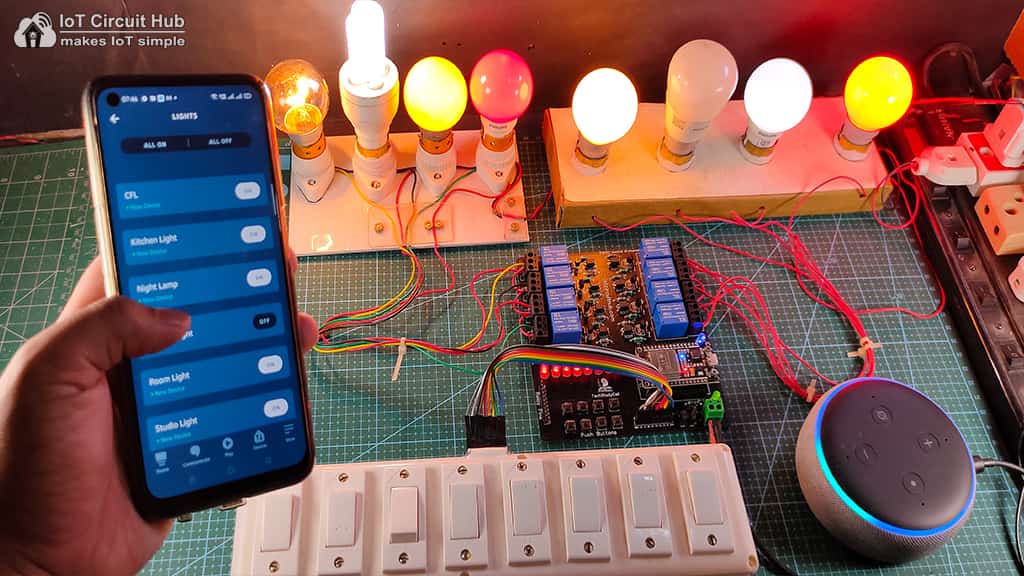
Now, you can control all the 8 home appliances from the Alexa app and also monitor real-time feedback if the ESP32 is connected with the WiFi.